Continue to Site

Welcome to EDAboard.com

Welcome to our site! EDAboard.com is an international Electronics Discussion Forum focused on EDA software, circuits, schematics, books, theory, papers, asic, pld, 8051, DSP, Network, RF, Analog Design, PCB, Service Manuals... and a whole lot more! To participate you need to register. Registration is free. Click here to register now.

Show a negative voltage 16F887 MikroC

Status
Not open for further replies.

Nev

Newbie level 3
Newbie level 3
Joined
May 20, 2013
Messages
3
Helped
0
Reputation
0
Reaction score
0
Trophy points
1,281
Activity points
1,304
Hi,
Could i please have some code help with 16F887, i have the mikroC voltmeter project with LCD display working from 0-5v.

How can i get the display to read a negative voltage? I am using the unit to display a sensor, which goes into a negative reading.

Do i need to use a -VREF to get this.?

Thank you

Neville
 

You can adjust that 2,5V is 0V (center), and between 2,5V to 5V you measure positive, and between 0V to 2,5V negative values. This can be done with OpAmp and with firmware code adjustments.

Considering that you now have fewer steps for positive and negative for higher resolution use low voltage uC (1,8V) or better ADC with higher resolutions.


Best regards,
Peter

;-)
 

Hi Peter,
I am trying to use the voltmeter to measure a loadcell, i put the loadcell through an amplifier circuit and am happy with the results on the LCD, i have a +5v and -5v that i can use, the firmware code i am not sure how to go about it, could you give me some help in this regards.

Thank you
Neville
South Africa
 

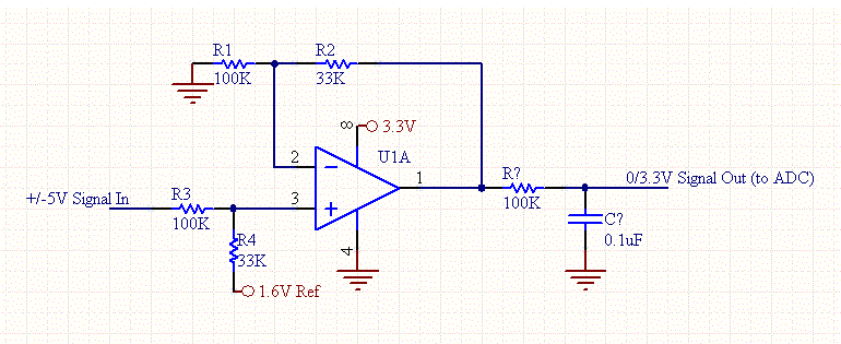
uC ADC measure in 0-5V range, or 1,8V, 3V respectively to uC voltage. You need to offset voltage -5V/+5V to 0-5V.

See example:

https://www.daycounter.com/Circuits/OpAmp-Level-Shifter/OpAmp-Level-Shifter.phtml

OpAmp-Level-Shifter.gif
 

Hi Neville sorry I was busy.

Here is fast code example. I make this on EasyPIC7 development board, code is nothing special and I test it on PIC18F45K22, you need just to adjust 2x16 LCD and ADC port (RA1) pins if you have different configuration. Code works 100%.

Include MikroE libraries (ADC, Conversions, LCD, LCD_Constants).

-5V == 0 == +5V to uC ADC 0 == 5V

Code:
/*

ADC 10-bit 0-5V Offset -5V - 0 - +5V

0-5V     0   1,25V  2,5V 3,75V  5V
Steps    0   256    512  768    1024
Offset   -5V -2,5V  0    +2,5V  +5V

Positive formula:
((adc_steps*0.00488)*1000)-(((1023-adc_steps)*0.00488)*1000)

Negative formula:
(((1023-adc_steps)*0.00488)*1000)-((adc_steps*0.00488)*1000);

*/


// Lcd module connections
sbit LCD_RS at LATB4_bit;
sbit LCD_EN at LATB5_bit;
sbit LCD_D4 at LATB0_bit;
sbit LCD_D5 at LATB1_bit;
sbit LCD_D6 at LATB2_bit;
sbit LCD_D7 at LATB3_bit;

sbit LCD_RS_Direction at TRISB4_bit;
sbit LCD_EN_Direction at TRISB5_bit;
sbit LCD_D4_Direction at TRISB0_bit;
sbit LCD_D5_Direction at TRISB1_bit;
sbit LCD_D6_Direction at TRISB2_bit;
sbit LCD_D7_Direction at TRISB3_bit;
// End Lcd module connections


unsigned int adc_rd, display_volt;
long adc_steps, adc_volt;
char dis_adc_volt[4], dis_adc_steps;


void main() 
{
  Lcd_Init();
  Lcd_Cmd(_LCD_CLEAR);
  Lcd_Cmd(_LCD_CURSOR_OFF);

  ANSELA = 0x02;             // Configure RA1 pin as analog
  TRISA = 0x02;              // Set RA1 pin as input

  while (1) 
        {
        adc_rd = ADC_Read(1);    // get ADC value from 1st channel (10-bit for PIC18F45K22)
        adc_steps = adc_rd;

        WordToStr(adc_steps, dis_adc_steps);
        Lcd_Out(1,5,dis_adc_steps);


        //Positive value from 512 to 1023 steps
        if (adc_steps > 512)
           {
           Lcd_Chr(2,4,' ');    //Delete negative symbol '-'
           adc_volt = ((adc_steps*0.00488)*1000)-(((1023-adc_steps)*0.00488)*1000);

           WordToStr(adc_volt, dis_adc_volt);

           Lcd_Chr(2,5,dis_adc_volt[1]);
           Lcd_Chr(2,6,',');
           Lcd_Chr(2,7,dis_adc_volt[2]);
           Lcd_Chr(2,8,dis_adc_volt[3]);
           Lcd_Chr(2,9,dis_adc_volt[4]);
           Lcd_Chr(2,10,'V');

           if (adc_steps < 522) Lcd_Chr(2,8,'0');
           if (adc_steps < 532) Lcd_Chr(2,7,'0');
           if (adc_steps < 717) Lcd_Chr(2,5,'0');
           }

        //Negative value from 0 to 512 steps
        if (adc_steps < 512) 
           {
           Lcd_Chr(2,4,'-');    //For negative voltage to add prefix '-'
           adc_volt = (((1023-adc_steps)*0.00488)*1000)-((adc_steps*0.00488)*1000);

           WordToStr(adc_volt, dis_adc_volt);

           Lcd_Chr(2,5,dis_adc_volt[1]);
           Lcd_Chr(2,6,',');
           Lcd_Chr(2,7,dis_adc_volt[2]);
           Lcd_Chr(2,8,dis_adc_volt[3]);
           Lcd_Chr(2,9,dis_adc_volt[4]);
           Lcd_Chr(2,10,'V');

           if (adc_steps >= 410) Lcd_Chr(2,5,'0');
           if (adc_steps >= 502) Lcd_Chr(2,7,'0');
           if (adc_steps >= 511) Lcd_Chr(2,8,'0');
           }


        Delay_ms(1000);

        }

}

LCD Screenshots:

First row shows number of ADC steps, and second voltage.

LCD Screenshot 1023 step.jpg LCD Screenshot 1 step.jpg

LCD Screenshot 256 step.jpg LCD Screenshot 512 step.jpg

LCD Screenshot 768 step.jpg


Best regards,
Peter


:wink:

- - - Updated - - -

My advice is to consider switching from PIC16F to PIC18F serie of uC.

For testing use 10K potentiometer with 220R resistor in serie with potentiometer. One side of pot connect to Gnd, other side connect to Vcc-uC and middle pin connect to resistor 220R then to ADC pin (I use RA1 uC pin).
 
  • Like
Reactions: Nev

    Nev

    Points: 2
    Helpful Answer Positive Rating
Thank you very much Peter, i do really appreciate your prompt help, i will set-up the pic 18F and try this.

Very best regards,

Neville
 

No prob, I'm glad to help you.

First try 0-5V to ADC input with usage of described 10K potentiometer and 220Ω resistor on ADC input pin, then try OpAmp configuration with input -5V 0 +5V and output 0-5V.

As additinal to this you can use small 5,1V-5,6V zener to ensure protection of ADC pin.


Best regards,
Peter

:wink:
 

Status
Not open for further replies.

Similar threads

Part and Inventory Search

Welcome to EDABoard.com

Sponsor

Back
Top