Continue to Site

Welcome to EDAboard.com

Welcome to our site! EDAboard.com is an international Electronics Discussion Forum focused on EDA software, circuits, schematics, books, theory, papers, asic, pld, 8051, DSP, Network, RF, Analog Design, PCB, Service Manuals... and a whole lot more! To participate you need to register. Registration is free. Click here to register now.

Need 4 time ON-OFF relay circuit

Status
Not open for further replies.

l2adiant

Junior Member level 1
Joined
Apr 17, 2013
Messages
15
Helped
0
Reputation
0
Reaction score
0
Trophy points
1,281
Visit site
Activity points
1,375
guys i need a 2 circuit the one is
when power applied the timer will trigger and the relay will remain off
when the timer runs out the relay will turn on and close the 2nd ciruit

and the 2nd circuit should b ON/OFF relay drive 4 times only and the ON/OFF

delay should be adjustable, after 4 time repeatation it should stopped
 

Hi l2adiant
You'll have to path for going through .
1- An analog way ( with some analog timers and some auxiliary circuits )
2- A digital way ( with an MCU )
Which one do you prefer ?
Best Wishes
Goldsmith
 

guys i need a 2 circuit the one is
when power applied the timer will trigger and the relay will remain off
when the timer runs out the relay will turn on and close the 2nd ciruit

and the 2nd circuit should b ON/OFF relay drive 4 times only and the ON/OFF

delay should be adjustable, after 4 time repeatation it should stopped


Analog would b fine so i will b able to get parts easily, please send me circuit design actually i want to use it in power generator auto start

- - - Updated - - -

you can use 555 time in astable multivibrator mode. (analog way)

- - - Updated - - -

you can use 555 time in astable multivibrator mode. (analog way)

I know 555 ic will use but plz post the circuit
 

you can find monostable multivibrator circuit on 555 datasheet itself (sorry i told astable mulivib. before it was wrong.. it shoud be monostable multi vibrator)

for the other part of circuit lets strt discussion?
have you any idea about your device?
can you post block diagram for it?
 

you can find monostable multivibrator circuit on 555 datasheet itself (sorry i told astable mulivib. before it was wrong.. it shoud be monostable multi vibrator)

for the other part of circuit lets strt discussion?
have you any idea about your device?
can you post block diagram for it?

please can u post the circuit?????

actually i want to activate 2nd circuit when electricity (220v) goes off then then 2nd circuit (ON/OFF) should b activate, it will try to start self start generator (in 4 tries) i hope you got what i want to design now
 

Maybe you can find something useful from this

Sequential Timers - Testing Your Circuit
**broken link removed**

Sequential Timer Circuit Diagram using NE555 Precision Timer IC
**broken link removed**
 

ok i will try to make circuit for yuo.. but explain me some conditions..
as per i am understanding your requirement that you want to make..

part A that will check for mains voltage. if mains goes down it will start PART B after some time.

now when part b starts it will toggle relay for 4 times...

M I RIGHT??
 

Hi and greetings to all
Is the problem solved ? if no i can guide too .
actually i want to activate 2nd circuit when electricity (220v) goes off then then 2nd circuit (ON/OFF) should b activate
It can be harvested by a simple diode and a simple command signal through a relay or triac . which section is the problem now ?
Best Wishes
Goldsmith
 

ok i will try to make circuit for yuo.. but explain me some conditions..
as per i am understanding your requirement that you want to make..

part A that will check for mains voltage. if mains goes down it will start PART B after some time.

now when part b starts it will toggle relay for 4 times...

M I RIGHT??

yea thats exactly what i want
 

Maybe you can find something useful from this

Sequential Timers - Testing Your Circuit
**broken link removed**

Sequential Timer Circuit Diagram using NE555 Precision Timer IC
**broken link removed**

i think it will work fine, but please can u explain how i can attach relay, actually im not much expert i can just put up things as described in circuit, so i'd b happy if u can tell me how to add relay there
 

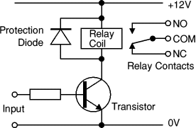
On output you can connect this circuit (output control transistor base over resistor):

diopro.gif
 

basically relay has 3 kijd of connections you need to know..
there should be 2 pins for input supply... (voltage rated)
upon giving supply to these pins a coil will magnetize and it will attract common contact to NO(normally open) contact..
upon removing supply common contact will connects back to NC (normally close) contact, (spring action)

in your project you should take output from NC. as it will connected to common when input is not there..so if mains fail your relay will be shorted COMMON to NC.

- - - Updated - - -

transistor would be needed if your input signal is too low to magnetize relay coil..
what is your input voltage? from where it comes?
i thought you are checking mains..

- - - Updated - - -

transistor would be needed if your input signal is too low to magnetize relay coil..
what is your input voltage? from where it comes?
i thought you are checking mains..
 

On output you can connect this circuit (output control transistor base over resistor):

diopro.gif


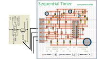
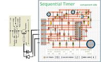
like this or should i have to add diode in each??? (if yes then in which direction?)

- - - Updated - - -

or like this????????


if any correction please let me know
 

when i switch on circuit only zero number led ON and remains on nothing else happen any solution for **broken link removed** ?????????
 

Status
Not open for further replies.

Part and Inventory Search

Welcome to EDABoard.com

Sponsor

Back
Top