Continue to Site

Welcome to EDAboard.com

Welcome to our site! EDAboard.com is an international Electronics Discussion Forum focused on EDA software, circuits, schematics, books, theory, papers, asic, pld, 8051, DSP, Network, RF, Analog Design, PCB, Service Manuals... and a whole lot more! To participate you need to register. Registration is free. Click here to register now.

dual FET control - how to drive gates?

Status
Not open for further replies.

electric1

Junior Member level 2
Joined
Apr 23, 2011
Messages
20
Helped
0
Reputation
0
Reaction score
0
Trophy points
1,281
Visit site
Activity points
1,507
Hello,

I am building a battery switch using low side topology, see schematic below. MCU has control lines at logic levels, one to drive Q2 to allow load , the other to drive Q1 to allow charge. If I use logic level gate type Q2 MOSFET, I can drive it directly via MCU line. But I can't figure out how to drive Q1 since its in reverse polarity in relation to MCU. Do I need to use high side gate driver with charge pump like **broken link removed** ?

Is there an easier/cheaper/better way? I don't have to use logic level MOSFETs, or I can use one logic level and one standard level if that works better.

BTW, the switch is not high frequency, so no concerns with switching speed, gate current, etc etc

Also, low side topology is not set in stone, I could change to high side if that makes it better. Low side was selected to make it easy to drive Q2 gate from MCU.

Thanks in advance...

dual FET control.jpg
 

Well, I don't understand your configuration of the MOSFETs.

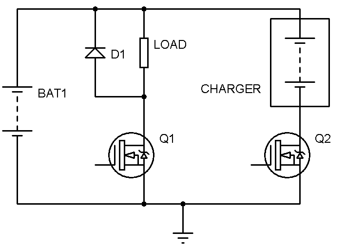
This is the configuration you should be using:

3881679700_1351800634.png


You don't need to use the diode if you're sure that you won't be using an inductive load. But, you might just let it be there. It won't harm if a non-inductive load is used.

Hope this helps.
Tahmid.
 

Tahmid,

thanks for your response. There are 2 issues with your schematic.

1. Due to the built-in diode in power MOSFETs Q2 cannot block charge current in your schematic, since charge current flows in opposite direction from load current.
2. Battery switch must have one set of terminals used for load and/or charge, so 2 MOSFETs must be in series, in the same circuit, and in opposite directions, so one can block load current and the other can block charge current.

Any other ideas?
 

Tahmid,

thanks for your response. There are 2 issues with your schematic.

1. Due to the built-in diode in power MOSFETs Q2 cannot block charge current in your schematic, since charge current flows in opposite direction from load current.

Hmm. Good point. Didn't notice that.

2. Battery switch must have one set of terminals used for load and/or charge, so 2 MOSFETs must be in series, in the same circuit, and in opposite directions, so one can block load current and the other can block charge current.

So, there'll be one set of terminals and they can be for the load or for charging?

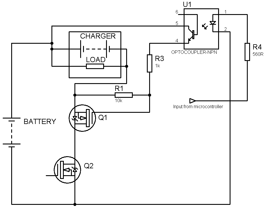
I've added the drive to your circuit and this should serve your purpose:

9678849300_1351804664.png


Hope this helps.
Tahmid.
 
Thanks for your help Tahmid. This might work, I need to test it, but it will cost 1-2mA of idle drain to power the LED, which is a problem in a battery powered application. I suppose my only other option is to use a high side gate driver IC.
 

The optocoupler only needs to be powered on during charging. So, when load is to be run from the battery, just keep the optocoupler off and you won't have any current draw by the optocoupler when running off battery.
 

Yes, but in that case Q1 is acting as a diode and causes voltage drop and heat losses under heavy loads.
 

But, when being powered off battery and driving the load, you can't turn Q1 on, at least not with this circuit. Current through the MOSFET can only be controlled from drain to source - it's a unidirectional switch. However, here current will be flowing from source to drain. Drive the MOSFET or not, current will pass through the diode.
 

Status
Not open for further replies.

Similar threads

Part and Inventory Search

Welcome to EDABoard.com

Sponsor

Back
Top