Continue to Site

Welcome to EDAboard.com

Welcome to our site! EDAboard.com is an international Electronics Discussion Forum focused on EDA software, circuits, schematics, books, theory, papers, asic, pld, 8051, DSP, Network, RF, Analog Design, PCB, Service Manuals... and a whole lot more! To participate you need to register. Registration is free. Click here to register now.

How can i use IGBT in parallel operation

Status
Not open for further replies.

aliraza786

Full Member level 4
Full Member level 4
Joined
Nov 10, 2009
Messages
210
Helped
14
Reputation
28
Reaction score
14
Trophy points
1,298
Location
Lahore, Pakistan, Pakistan
Activity points
2,914
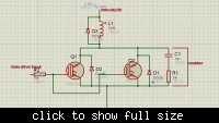
i am using 80N60 IGBT to drive my inductive load of resistance 6ohm.. i use 4N25 optocoupler to drive gate i use 20 volts supply for gate... system voltage is 300volts DC .. i give a pulse at the gate of IGBT for 100ms just... i want to operate 2 or more IGBT in parallel kindly guide me how can i use IGBT in parallel operation. is there any more requirements which should be fulfilled for paralleled operation.?


Re: parallel working of IGBT

- Equal current share will be hopefully achieved at high currents, at lower currents thermal runaway must be expected.
- Gate resistors should be better placed per IGBT.
- 10k is a very high gate resistor value, resulting in low switching speed
- driving IGBTs with a 4N25 without gate drivers (discrete transistors or ICs) isn't a good idea
- the effect of a 10k snubber is comparable to flyspeck

ok thnku so much... current will be 50 ampare at this current . current will divide equally.? this is just a diagram for showing connections. actual snubber is 10nf cap with 5 mega ohm resistor. and guide me more about gate driver and protection circuits. how can i make a good gate driver with protection. i want my igbt to protect from spikes and any other thing which damages it... thanks for your reply :)

and what is flyspeck.?
 

Re: parallel working of IGBT

IGBT type should be of positive temperature coefficient in parallel operation.
 

Re: parallel working of IGBT

I agree fully with FvM

I would recommend you to check the manufacturer website for application info on paralleling. Generally spoken, you have two types of IGBT, the ones that can be paralleled easily and the ones that are more difficult.

If you require isolation, use the optocoupler to drive an IGBT driver. An IGBT driver is a circuit that can deliver (source) current to the gate and extract (sink) current from the gate. If you can't sink current from the gate, the charge remains and the IGBT remains in on-state and in the end may go slowly to the off-state (generating smoke).

Though an IGBT has "bipolar transistor" in its name, the input is a mosfet, so to gain knowledge on driving IGBT's, you may also look to articles on mosfet drivers.

A snubber is used to make sure the IGBT voltage and current stays within the save operating area and to divert some of the losses to the snubber resistor (so the IGBT runs cooler). There are snubber topologies that can recover part of the switching loss (instead of dissipating it in the resistor).

Actual snubber design depends on your real application and how fast you drive the IGBT. I think if you do some web search you will find articles on snubber design.
 

Re: parallel working of IGBT

and what is flyspeck?
A small piece of dirt, in other words something that has no effect in an electrocic circuit. But 5 megaohm is even less noticeable. One would expect a level 100 to several 1000 ohms for an effective snubber in the present case, resistor power ratings should be respectively. A snubber can be helpful, if the circuit wiring is bad and can't be easily improved.

this is just a diagram for showing connections.
I see. Without knowing the actual device wiring, I won't dare substantial statements about circuit operation anyway.

and guide me more about gate driver and protection circuits
People would use a low impedance gate driver, e.g. an industry standard driver IC like TC42x and gate resistors in a 10 ohms order of magnitude.
With reasonable circuit wiring, there won't be a spike problem.

current will be 50 ampare at this current . current will divide equally.?
I don't even know which 80N60 type you are exactly using. There are different ones. But I won't expect that unequal current share is the primary problem.

By the way, operation mode hasn't be told at all? Switching frequency, duty cycle?
 

Re: parallel working of IGBT

A small piece of dirt, in other words something that has no effect in an electrocic circuit. But 5 megaohm is even less noticeable. One would expect a level 100 to several 1000 ohms for an effective snubber in the present case, resistor power ratings should be respectively. A snubber can be helpful, if the circuit wiring is bad and can't be easily improved.


I see. Without knowing the actual device wiring, I won't dare substantial statements about circuit operation anyway.


People would use a low impedance gate driver, e.g. an industry standard driver IC like TC42x and gate resistors in a 10 ohms order of magnitude.
With reasonable circuit wiring, there won't be a spike problem.


I don't even know which 80N60 type you are exactly using. There are different ones. But I won't expect that unequal current share is the primary problem.

By the way, operation mode hasn't be told at all? Switching frequency, duty cycle?

thanku so much for your help.. there is just 300ms pulse and then ground... when ever user press button just 300ms pulse will go at gate... and sir i got the resion of why my IGBT burn... IGBT is not fully on when i apply 20 volts at gate... there is much drop acros Collector emitter junction... i use low voltage testing. i give 6 volts to 10 ohm resistor and 2nd terminal of resistor is attached to the collector and emitter is grounded. i give 20 volts at gate and IGBT is not fully on still 4 volts drop across collector emitter junction.. and if i increase voltage at gate drop across collector emitter junction reduces.. i have to go for TC42x chip... my teacher told me that if collector voltage is 300 volts then gate should be at 320 volts for proper switching.. is that thing is correct.? because such chips use bootstrapping capacitor which increases the voltage at gate more then the collector volatge... thanks for your help
 

Re: parallel working of IGBT

my teacher told me that if collector voltage is 300 volts then gate should be at 320 volts for proper switching.. is that thing is correct.?
Any IGBT will be destroyed with Vge > 30V. Your teacher is probably thinking of an IGBT connected as high-side switch.

Your Vce.sat measurement makes no sense however. A Vgs voltage of 12 or maximum 15 V is sufficient for all IGBTs. There must be something completely wrong with your measurement setup or IGBT.

Are you sure that you have really 20V Vgs?
 

Re: parallel working of IGBT

Any IGBT will be destroyed with Vge > 30V. Your teacher is probably thinking of an IGBT connected as high-side switch.

Your Vce.sat measurement makes no sense however. A Vgs voltage of 12 or maximum 15 V is sufficient for all IGBTs. There must be something completely wrong with your measurement setup or IGBT.

Are you sure that you have really 20V Vgs?

yeah FVM sir i give 2o volts at gate . i upload video of my testing... my instrument is new and branded... and all other measurements are correct from this instrument... in my configuration i am using as low side driver right.? which needs almost 20 volts for switching.? my IGBT is 80N60 and i use a new piece..
 

Re: parallel working of IGBT

I still wonder about the exact IGBT type, I know e.g. 80N60 from IXYS. But at Ic = 0.6A (6V/10 ohm load) and Vge > 10V, Vce.sat will be below 1V for any IGBT.
 

Status
Not open for further replies.

Similar threads

Part and Inventory Search

Welcome to EDABoard.com

Sponsor

Back
Top