Continue to Site

Welcome to EDAboard.com

Welcome to our site! EDAboard.com is an international Electronics Discussion Forum focused on EDA software, circuits, schematics, books, theory, papers, asic, pld, 8051, DSP, Network, RF, Analog Design, PCB, Service Manuals... and a whole lot more! To participate you need to register. Registration is free. Click here to register now.

[SOLVED] Variable frequency generator using a 555 timer chip

Status
Not open for further replies.

Faddei

Junior Member level 2
Joined
Dec 20, 2007
Messages
23
Helped
0
Reputation
0
Reaction score
0
Trophy points
1,281
Activity points
1,458
Hi

i would like to make an frequency generator using a 555 timer chip. The frequency should vary in the range of 100hz to 1kHz with a reasonable duty cycle (20-80%). I am using the circuit below. Varying r2 alone would not do the job because at r2=0 the duty cycle is 100%.

I found out if i started with r1=2k2 and r2=4k7 and c=1uF. The freq =124hz and duty cycle is 60%.
At r1=700R r2=200R c=1uF. The freq=1309hz and the duty cycle is 81%.

But i cant find a way to change both resistors with one potentiometer. Is there a way to do that or should i use a different topology?

Thank you in advance
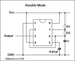
555astablemode.gif
 

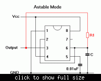
There is a simpler topology with only one resistor. It has a duty cycle close to 50%. See the changed picture below.

 
There are a few tricks you can try, to obtain a variable duty cycle. Some are at this link:


One method uses a potentiometer dialing a position between two diodes arranged in anti-parallel.

Another method uses a 556 dual timer IC. You select frequency with one 555 and the pulse length with the other.
 

There is a simpler topology with only one resistor. It has a duty cycle close to 50%. See the changed picture below.


I am simulating this option and it does not seem to work. Shouldnt pin 7 be connected to something?
 

Shouldnt pin 7 be connected to something?
No. In your original circuit pin 2, pin 6 and the capacitor were driven by pin 7 and a pull-up resistor. Now they are driven by the output (pin 3) instead.

It should work. If you vary the resistor between say 10K and 100K, it should give a frequency range of about 10 to 1.
 
  • Like
Reactions: Faddei

    Faddei

    Points: 2
    Helpful Answer Positive Rating
Thanks guys. This porblem is solved.
 

I want to generate frquency from 17 Hz to 17KHz. how to calculate frquency by above circuit?
can anyone sugges me the values of R and C?
Please reply
 
Last edited:

I want to do it by one resistor. and transistor for what purpose? I am using this frequency in one unit called tachometer calibrator
 
Last edited:

Now please help me to do that.. I have used 100k pot and 1uf capacitor. Now for 84.70k I got 17Hz but for 17KHZ it should be 84.70ohm but by 100k pot its not possible to achieve 84.70ohm. I am trying another calculation. If you got any idea then please tell. And one another thing by these values only on time is of required frequency but i want total on time +off time equal to 17 Hz to 17KHz
 

A good way is to use 3 capacitors, say 1uF, 100nF and 10 nF, with a switch to select which capacitor is in circuit. Then put a resistor of say 6K8 in series with the potentiometer to limit the frequency range for each switch position.

That should give frequency ranges of about 15Hz to 200Hz for the first switch position, 150Hz to 2000Hz for the second switch position, and 1500Hz to 20000Hz for the third switch position
 
Status
Not open for further replies.

Part and Inventory Search

Welcome to EDABoard.com

Sponsor

Back
Top