Continue to Site

Welcome to EDAboard.com

Welcome to our site! EDAboard.com is an international Electronics Discussion Forum focused on EDA software, circuits, schematics, books, theory, papers, asic, pld, 8051, DSP, Network, RF, Analog Design, PCB, Service Manuals... and a whole lot more! To participate you need to register. Registration is free. Click here to register now.

Need a solid state fuse

Status
Not open for further replies.

boylesg

Advanced Member level 4
Joined
Jul 15, 2012
Messages
1,023
Helped
5
Reputation
10
Reaction score
6
Trophy points
1,318
Location
Epping, Victoria, Australia
Activity points
11,697
Is it possible to produce a solid state fuse with minimal and simple components to retro fit to a multimeter at its regular fuse holder?

I don't mind drilling a couple of small holes in the case for any wires to an external circuit board if necessary.
 

If you burn your multimeter fuse so frequently you are probably doing something wrong so you should reconsider your methods or be more careful while using it.
 

Yes I agree with Alex You doing something wrong if this is often stiruation. I have only one need to change 200mA fuse in multimeter.
 

Yes, it should theoretically be possible. Multimeters use a fast blow fuse, though, so a proper replacement would require fast circuitry. From what I've seen, it seems the fast-blow fuse in multimeters respond to over-current within several hundred microseconds. I don't think a PTC fuse would suffice, as it relies on the temperature change of a device which is in good thermal contact with the PCB—i.e., its thermal time constant is relatively slow.

In my mind, you'd probably want to go for a low-Rds MOSFET to carry the current, in series with a current sense resistor, across which a comparator is placed to turn the MOSFET off when over-current has been reached. You'd want it to have a latching action to keep it off (hysteresis), and then either a timer or a button to reset your "fuse."

Perhaps it would be insightful for you to describe why you want to do this.
 

I have only one need to change 200mA fuse in multimeter.

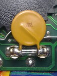
You could use a self-resetting PTC fuse, also called varistor or metal-oxide-varistor (MOV), see e.g. **broken link removed** ( <-- direct PDF download).

I've used such a MOV successfully in my DMM for many years: PTC_resettable_fuse-radial.jpg
 
I must say, that this situation is not normal and common in using of multimeter instruments.

First when you measuring some current you check that is value in range of instrument capabilities.

Then put ammeter on multimeter on max, let say 10A. If you see that value is under 200mA or 0,2A, then you can switch on 200mA range on multimeter to get better resolution.

Its not good to start measuring unknown value in circuit from 200mA range.
 

So I don't have to open open it up to change the fuse.

The DMM seems a hell of a lot more sensitive to over current than my old AMM is. With the AMM the needle goes off scale if you happen to have the range to low and then you just increase the range and no problems.

Every time I stuff up with the DMM I have to change the fuse......pain in the arse.

I read about thermoresistor based resettable fuses but the best I have found is 200mA one with a 400mA trip current and 2s blow time.

My instinct told me that was not enough and your post would seem to confirm that.

Thought about a lower rated one e.g. 100mA with a 200mA trip current but then the increasing resistance below 200mA would probably interfere with the DMM readings.

- - - Updated - - -

You could use a self-resetting PTC fuse, also called varistor or metal-oxide-varistor (MOV), see e.g. **broken link removed** ( <-- direct PDF download).

I've used such a MOV successfully in my DMM for many years: View attachment 77648

What rating was the original fuse and what was the rating of the PTC fuse you replaced it with?

- - - Updated - - -

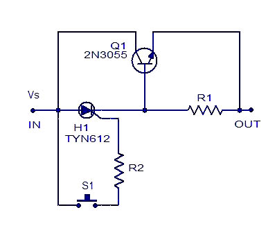
You can try out this.It needs resetting using a switch after every trip.
http://www.circuitstoday.com/simple-elecronic-fuse

Cool! Will give this a go. No doubt has a quicker 'blow' time than the varister based fuses seem to have.

Tried for a while to find something like this with google but failed. Looks as though it would be possible to fit this inside the DMM.

I can't see that I would need the reset switch though. Because removing the DDM probes from the circuit under test would have the same effect as hitting that reset switch.
 
Last edited:

Every time I stuff up with the DMM I have to change the fuse......pain in the arse.

You are joking I guess ? :shock:


This suggested circuit can be little to have small original fuse dimension and socket connection the same as fuse.

Use SMD thyristor, transistor, resistor.


But I dont understand all of this, I mean why you need this.
 
Last edited:

So I don't have to open open it up to change the fuse.
...
Every time I stuff up with the DMM I have to change the fuse......pain in the arse.

You could just run some wire from the internal fuse terminals outside the case and mount the clip there, but that could have potential safety issues if you don't cover it. You could also just tape your screwdriver and a bag of fuses to your DMM so it's always handy when you need it.

But I have to agree with the above. It's not normal to go through fuses that fast. Even if you do your fuse modification, your time would be better spent training yourself on safe and proper use of the DMM.

None of this will help you not blow up other people's DMMs for example.

Since I purchased my DMM about 6 or 7 years ago, I've had to change the 500mA fuse exactly twice -- the first time was when a friend borrowed it and tried to measure 220VAC in some incorrect mode, the second time was the following day when he did the exact same thing again. :|

J
 
  • Like
Reactions: FvM

    FvM

    Points: 2
    Helpful Answer Positive Rating
Erikl, are you sure the PTC is a MOV? MOV is a high voltage clamping device (like a zener diode), not current limiting device. A PTC current limiter device works generally by having pieces of carbon touching inside a special plastic matrix (the "polymer" part of the polyswitch name). Current is carried through the carbon pieces. When the carbon gets hot due to excessive current, the plastic matrix expands and the carbon doesn't touch anymore - no current.

I have a circuit suggestion:
IXTP6N50D2 is a "depletion mode" fet; 500V TO220 package. If you put something like -2.5V to -4.5V on gate (Vgsoff spec), the mosfet turns off. Put 10 ohm resistor from gate to source. So the circuit is: Drain = one end of "fuse", Gate = other end.
If 400mA flows through fet and resistor, then -4V is developed across the resistor and also the gate-to-source; -4V on g-s means fet is off. So actually, the circuit works as a current limiter at some current between 0 and 400 mA. You'll have to try different resistors to get the current limiting you want.

This circuit only works + to -, so you have to put another in series facing the other way.

I am proposing 500V part so your meter can withstand 220V line, but you have to watch power dissipation (100v*.4A = 40W - about 1 second life for mosfet). Maybe you can put erikl's PTC in series as well: fast transient done by fet, sustained overcurrent limited by the PTC.

- - - Updated - - -

If you burn your multimeter fuse so frequently you are probably doing something wrong so you should reconsider your methods or be more careful while using it.

Haha, Alex - It happens to me when I let other people use my meters. What's really amazing is that it even happens on my HP974A's which have a shutter that covers the Amp jack if the meter isn't set for amps!
 

Maybe is better for you to stay at analog needle.


We didnt ask you, that DMM is not defective ?
Maybe you have some short circuit inside, cased by maybe battery leaking or something else.
 

Maybe is better for you to stay at analog needle
Well I aint gonna learn anything new if I don't try. If I blow the fuse 100 times then I blow the fuse 100 times! Sooner or later I will develop more appropriate habits for the DMM.

But if I can get the previously posted solid state fuse working then all the better.


We didnt ask you, that DMM is not defective ?
Maybe you have some short circuit inside, cased by maybe battery leaking or something else.

I don't think so. It works just fine on current as long as I remember to always switch the dial and + probe back to the high range before testing a new input.

It is a simple matter of having developed bad habits I suppose after using the vastly more forgiving AMM for years.

I pulled a triac off a tv circuit board at one stage and pondered why you would use such a device rather than a transistor. Now I know!

I love this $hit.....soaking up new knowledge.
 
Last edited:

I don't think so. It works just fine on current as long as I remember to always switch the dial and + probe back to the high range before testing a new input.

It is a simple matter of having developed bad habits I suppose after using the vastly more forgiving AMM for years.

That explain often fuse replacement. I cant imagine what happen with oscilloscope then. :smile:


There is possibility to put this suggested circuit into fuse body, except taster which will be outside. All parts should be SMD.

Its possible, but I think its better to change bad habits when using fine instruments.


electronic-fuse.jpg
 

Often the if the ESR is increased in a circuit, any added Rs would reduce the current, unless relatively small.

Car's now use integrated Hall sensors on a tiny shunt loop for directional or bi-directional current sensing from low to 100's of Amps.

I used Kelvin shunts with orthogonal coax sensing of taps across large conductors. similar methods for measuring 100KA in diffusion welders.

For DC currents , I still prefer the analog Amp meters like the one I had in my 63' MGB with +/-30A scale and <1A resolution.
You can modify any 50uA meter with the appropriate copper shunt.

When sensing PWM, you have be concerned about inductive shunts and wires, so the area of the loop current needs to be nulled if possible with twisted pair wire.

But if it PTC works great. It's bidirectional but have a much larger resistance than a fuse.

For Lab work a good 4 Digit Kelvin DMM is a handy tool.

For vector transient or AC, V vs I readings, I prefer to multiply the signals in real-time on a DSO, using Tek. Diff. Probes. for current or the Hall method CUrrent probe and 10:1 probe for voltage in A x B Calc. mode.

But when desperate, I may resort to a DMM amp meter oh hope the fuse is still working.
 

There is possibility to put this suggested circuit into fuse body, except taster which will be outside. All parts should be SMD.

Its possible, but I think its better to change bad habits when using fine instruments.


electronic-fuse.jpg

Taster? SMD?

- - - Updated - - -

Taster? SMD?

Couldn't get TYN612 but from the datasheet it is heavy duty and can handle high currents. However I don't need such a heavy duty component for this purpose.

I was able to get a couple of these from the local jaycar to play around with: **broken link removed**

Have set myself up a series of resistors that deliver below 200mA, 200mA exactly and above 200mA.

So this has to be set up for a fixed voltage which you don't have with a multimeter.

So I might have to get it working with 9V in and then figure out how to set it up with a potentiometer in place of R1.

If it is set up for 12V and you measure 9V then it is going to let through more than 200mA isn't it.
 
Last edited:

S1 is taster. Just one hole drilled on multimeter plastic case.

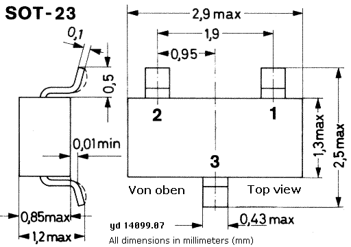
sot23.gif


Thyristor, transistor exist in SOT23 SMD case.

Resistor in SMD lets say 0805.


I hope that you didnt mean really to put 2n3055 transistor for this.


Dont let that this resseting fuse be bigger then multimeter. Yes you can also use TO92.

The transistor was a bit of a monster too with ratings far higher than needed in this instance. I was going to try this using a 2SC1815 as I have a heap of these salvaged from circuit boards.

If this device 'blows' with the multimeter leads connected to a test circuit then what happens to the BT169D if I removed the multimeter leads from the test circuit and the BT169D is powered down entirely. Surely it does not retain its off state even if re-connect the multimeter probes to the test circuit.

So the question becomes........

Do I need the reset part of the circuit at all for this application?
 

Status
Not open for further replies.

Part and Inventory Search

Welcome to EDABoard.com

Sponsor

Back
Top