Hassan Munir
Newbie level 6

- Joined
- Jan 27, 2012
- Messages
- 14
- Helped
- 0
- Reputation
- 0
- Reaction score
- 0
- Trophy points
- 1,281
- Activity points
- 1,409
Hi,
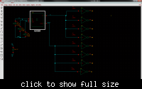
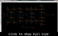
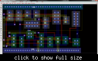
I created an adder layout as part of a university project using cadence virtuoso. Both DRC and LVS pass 100%. However when I simulate using my extracted view against my schematic view I see a huge discrepancy in terms of the output voltage swings( should be from 0 to 1.8V however extracted view gave me 0 to 500mV). I am using inverters at the output of both the sum and carry bits of the adder. The role of the inverters is to provide drive strength to the output to allow full voltage swing , so 500mV makes no sense. If LVS and DRC pass can there be reasons other than parasitic capacitance that can cause this issue. The lab required me to use metal 1 and metal 2 for routing. I followed manhattan routing so metal1 and metal2 are hardly ever parallel. So where could these parasitic effects come from?
Any help will be highly appreciated


