Continue to Site

Welcome to EDAboard.com

Welcome to our site! EDAboard.com is an international Electronics Discussion Forum focused on EDA software, circuits, schematics, books, theory, papers, asic, pld, 8051, DSP, Network, RF, Analog Design, PCB, Service Manuals... and a whole lot more! To participate you need to register. Registration is free. Click here to register now.

Which Is PGD & PGC Pins In PIC Microcontroller?

Status
Not open for further replies.

Code Warrior

Full Member level 4
Full Member level 4
Joined
Dec 30, 2004
Messages
230
Helped
10
Reputation
20
Reaction score
2
Trophy points
1,298
Visit site
Activity points
1,831
I want to programe PIC16F887, PIC16F886 and PIC16F690 using ICD-2.
I read data sheet but no where these PGD and PGC pins are mentioned. Please tell me which pins are PGD and PGC in above said controllers.
 

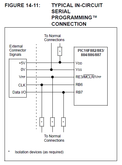
Reference: PIC16F882/883/884/886/887 Data Sheet, Section: 14.9 In-Circuit Serial Programming, Page: 228

0_1340522786.jpg


Reference: PIC16F882/883/884/886/887 Data Sheet, Section: 14.11 In-Circuit Debugger, Page: 229

14.11 In-Circuit Debugger

The PIC16F882/883/884/886/887-ICD can be used in any of the package types. The device will be
mounted on the target application board, which in turn has a 3 or
4 wire connection to the ICD tool.

When the debug bit in the Configuration Word (CONFIG<13>) is programmed to a ‘0’, the In-Circuit
Debugger functionality is enabled. This function allows simple debugging functions when used with
MPLAB® ICD 2. When the microcontroller has this feature enabled, some of the resources are not available
for general use. See Table 14-9 for more detail.

Note: The user’s application must have the
circuitry required to support ICD functionality. Once the ICD circuitry is enabled, normal device
pin functions on RB6/ICSPCLK and RB7/ICSPDAT will not be usable. The ICD circuitry uses these pins
for communication with the ICD2 external
debugger.

For more information, see “Using MPLAB® ICD 2”
(DS51265), available on Microchip’s web site
(www.microchip.com).

14.11.1 ICD PINOUT

The devices in the PIC16F88X family carry the circuitry for the In-Circuit Debugger on-chip
and on existing device pins. This eliminates the need for a separate die or package for the ICD
device. The pinout for the ICD device is the same as the devices (see Section 1.0 “Device Overview”
for complete pinout and pin descriptions). Table 14-9 shows the location and function of the ICD
related pins on the 28 and 40 pin devices.


Summary:

RB6/PGC/ICSPCLK
RB7/PGD/ICSPDAT

For all the requested PIC16Fs, refer to datasheet for exact pin numbers.

BigDog
 

Status
Not open for further replies.

Similar threads

Part and Inventory Search

Welcome to EDABoard.com

Sponsor

Back
Top