Continue to Site

Welcome to EDAboard.com

Welcome to our site! EDAboard.com is an international Electronics Discussion Forum focused on EDA software, circuits, schematics, books, theory, papers, asic, pld, 8051, DSP, Network, RF, Analog Design, PCB, Service Manuals... and a whole lot more! To participate you need to register. Registration is free. Click here to register now.

Poles and Zeros Bode Plot

Status
Not open for further replies.

TuAtAu

Advanced Member level 4
Full Member level 1
Joined
May 22, 2011
Messages
119
Helped
9
Reputation
18
Reaction score
9
Trophy points
1,298
Location
Jupiital
Activity points
2,149
Hi Guys,

I am learning compensation and I want to know the poles and zeros from a circuit.
I learn from simple circuit 1st to make myself have a strong foundation.

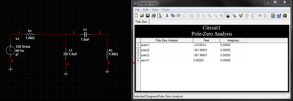
But when I see this circuit and do AC analysis and Poles Zeroes Analysis.
It make myself confuse...

From my calculation, there should be a cascade from (RC) (CR) low/high pass filter..
Their poles and zeroes should be multiply together.
2 poles at -1000 and 1 zero at origin from calculation..

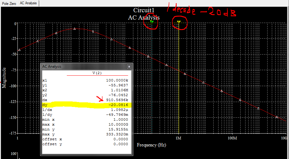
QUESTION: how come the simulator give me the unexpected answer??? Why give me 3 poles? but gain bode plot only -20dB/decade?
or my calculation is wrong?
99_1338865429.png
[/url]
41_1338865429.png
[/url]
 

Hi,

poles are not at w=-1000 because both RC-CR sections are not decoupled. That means: Both 1st order transfer functions must not be calculated separately. Instead, find the pole distribution from the 2nd order denominator of the combined transfer function.
The slope of this function always is +- 20 dB/dec. (The high pass makes the positive and the lowpass the negative slope).
 
  • Like
Reactions: TuAtAu

    TuAtAu

    Points: 2
    Helpful Answer Positive Rating
Hi LvW,

Thanks for point out the decoupling things for me to further research. :)


By the way, how about 3 poles from the picture? according to my understanding, each pole will give -20dB/decade, since there is a zero giving +20dB/decade from origin, 1st pole will make it 0dB/decade, 2nd pole will make it -20dB/decade and the 3rd pole should make it become -40dB/decade what.. how come the AC analysis still giving 20dB/decade?
 

By the way, how about 3 poles from the picture?

The shown circuit has only two poles.
For R1=R2=1k and C1=C2=1µF the poles are at: w1=-381.97 1/s and w2=2618 1/s .

I don`t know why you have found a third pole.
Regarding the slope of the transfer function:
* The zero makes +20 dB/dec
* The 1st pole reduces the slope to 0dB/dec
* The 2nd pole makes -20 dB/dec.
 
  • Like
Reactions: TuAtAu

    TuAtAu

    Points: 2
    Helpful Answer Positive Rating
ya I also curious about the 3rd pole..

maybe simulator bug? I caught a bug from a simulator!? Hurrey :p
 

Status
Not open for further replies.

Part and Inventory Search

Welcome to EDABoard.com

Sponsor

Back
Top