Vermes
Advanced Member level 4

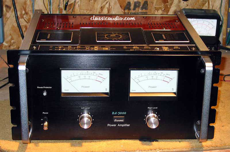
On the Internet, there are many interesting power amplifiers, both professional and amateur. This project was inspired by one of them – SANSUI BA-5000.
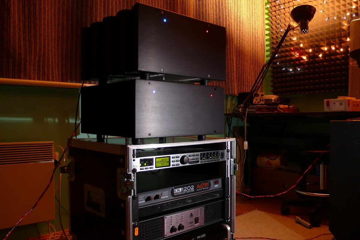
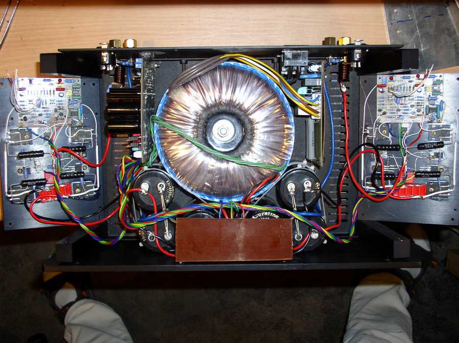
How it looks like:
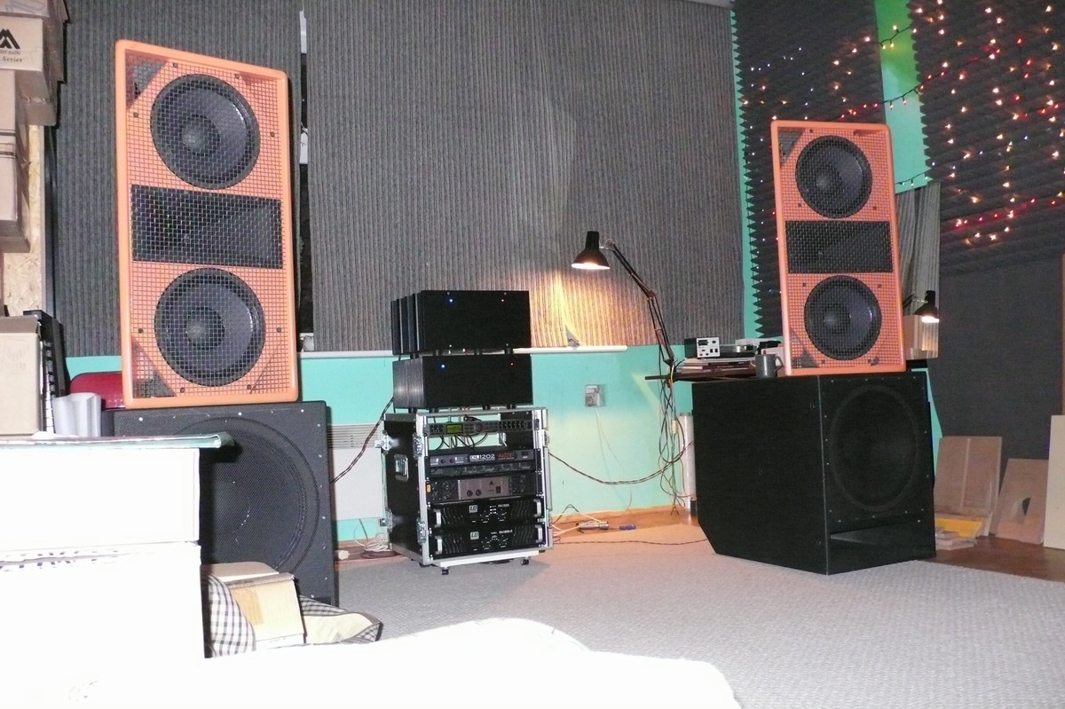
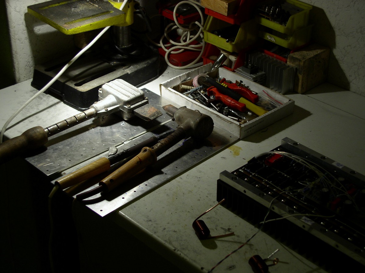
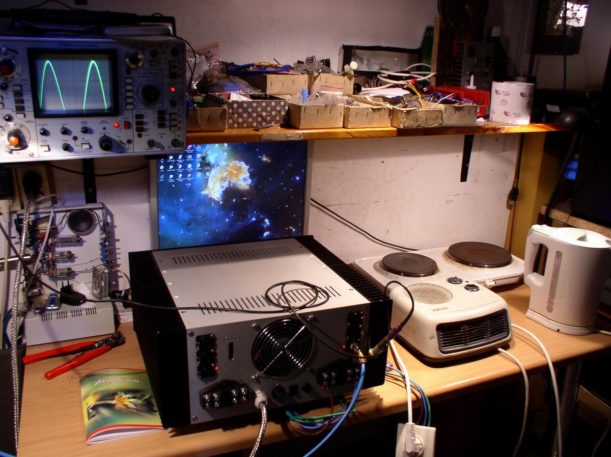
Tests: from the top – Aleph-X 2x100, below 4x750 and others:
To sound small parties, it would be good to use a home made construction. The idea was to create an amplifier, which is universal enough to serve for both home cinema and a party. This project is based on symmetric topology with two differential pairs at the input. You can read more about that at: LINK.
Krell KSA 50 and 100, Gryphon Tabu Century and Callisto, LC Audio Millenium amplifiers were based on that topology with small modifications.
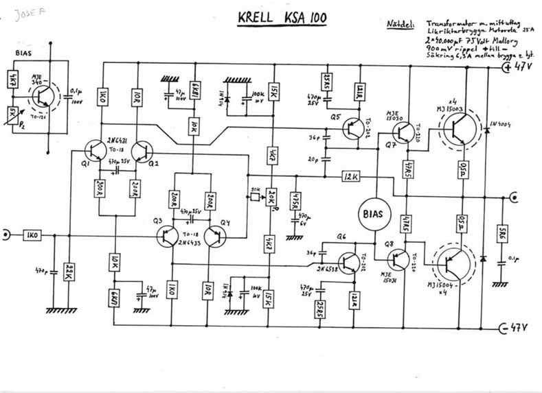
Krell KSA 100 - schematic.
Different kits of similar construction can be found on the Internet and are applied in this project. A test copy was made. It reached 2x190W/8 or 2x350W/4. A stabilized power supply of voltage part was used in that copy.
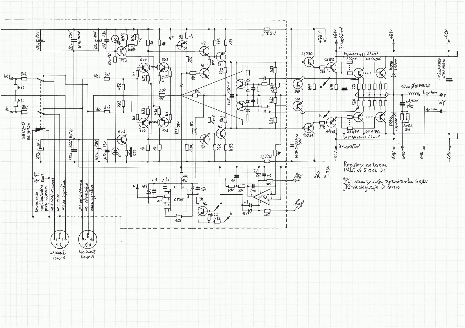
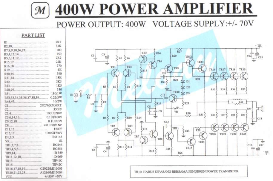
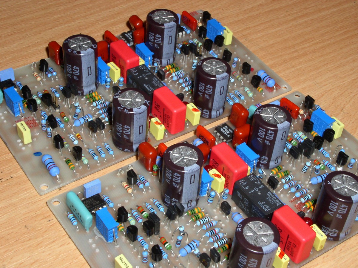
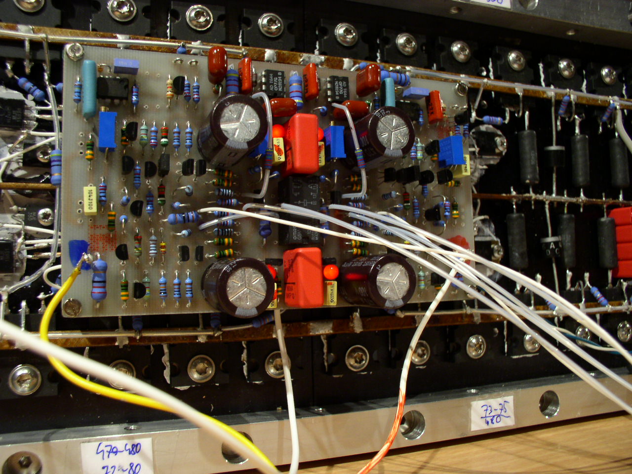
Schematic diagram of the amplifier (750W/2) – one channel.
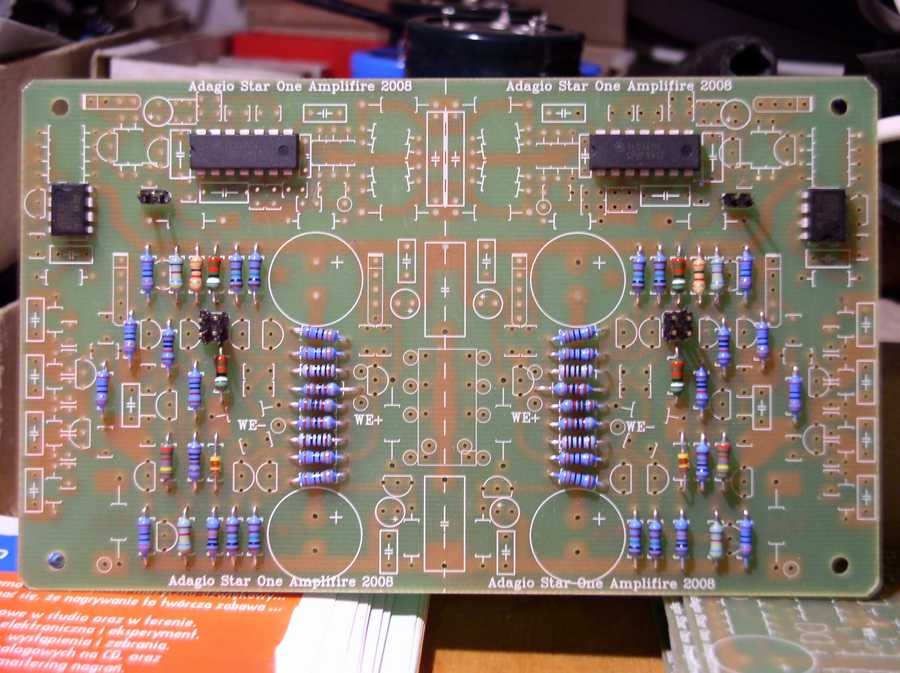
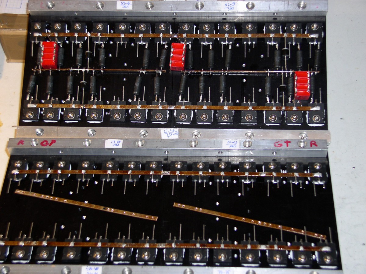
The amplifier is a simple device. It operates without a global feedback loop, there is a DC servo, protection against overload inspired by LC Audio Millenium, strengthening Ku=48dB and -20dB attenuator at the input: 8k2 in signal series and k82 to the ground. Only voltage part is mounted on the PCB. Transistors tips in groups of 6 pieces are selected on UBE and then on HFE, the tip on 2SC5200/SA1943, driver – the same pair, predriver on MJE15030/031, at the input ZTX653/753, next MPSA42/92. In the bias stabilization system – MJE340/350.
In the prototype copy there was no output current limiter, which is shown on the schematic without marked values of elements. Quiescent current was set to about 30mA for a pair of transistors. The voltage drop between points a and b is 12mV. Quiescent power taken by the whole amplifier is approximately 110W.

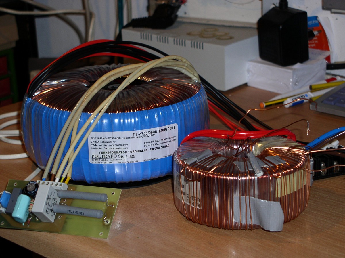
Power was 200W/8ohm with 6 output pairs applied. Initial grades of terminal are powered by 12V higher voltage in order to maximize usage of the main power supply. Toroidal transformer 3900VA was applied.
To ensure flexibility in adjusting to the conditions of supply, primary taps 215V-230V-245V were used in this project.
4 channels are loaded by 800W/2ohm each, all controlled by the same signal, could send in total 113A to the load in peak. The power supply should not drop below 58V then.
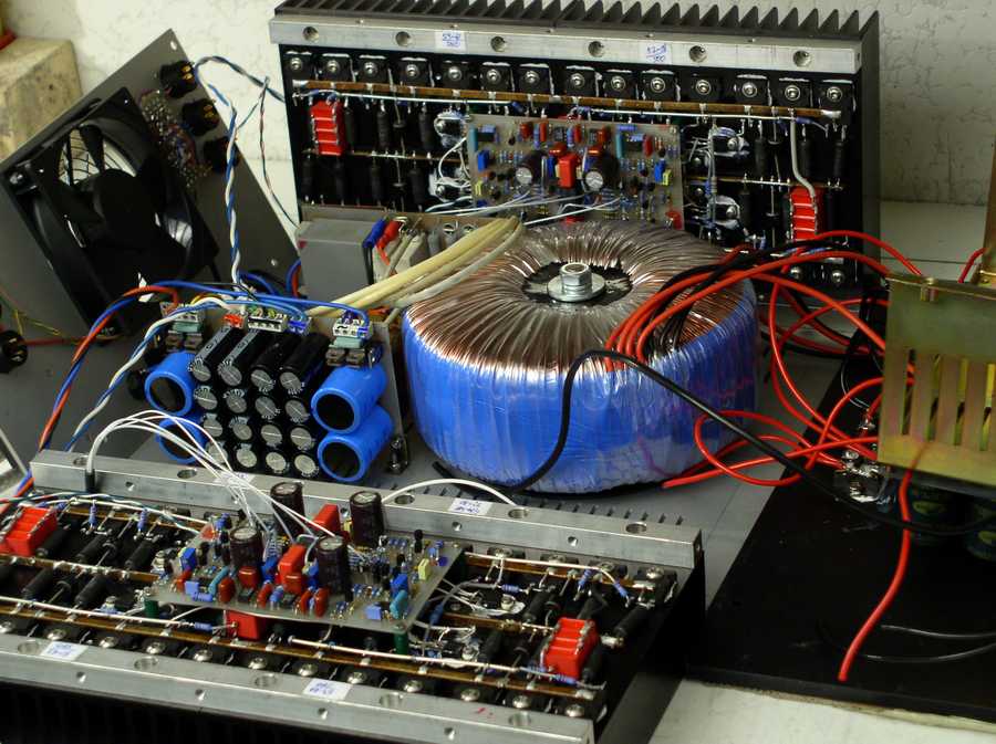
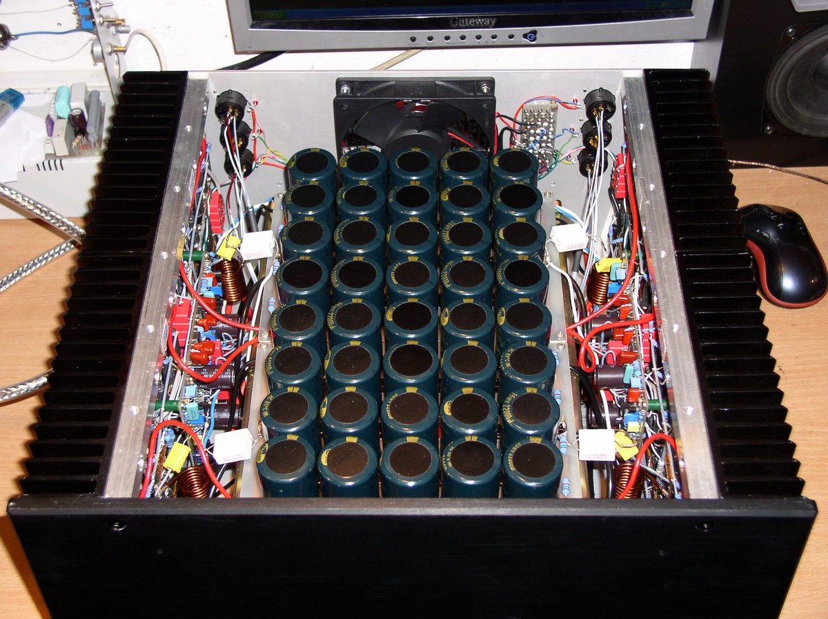
Capacitors:
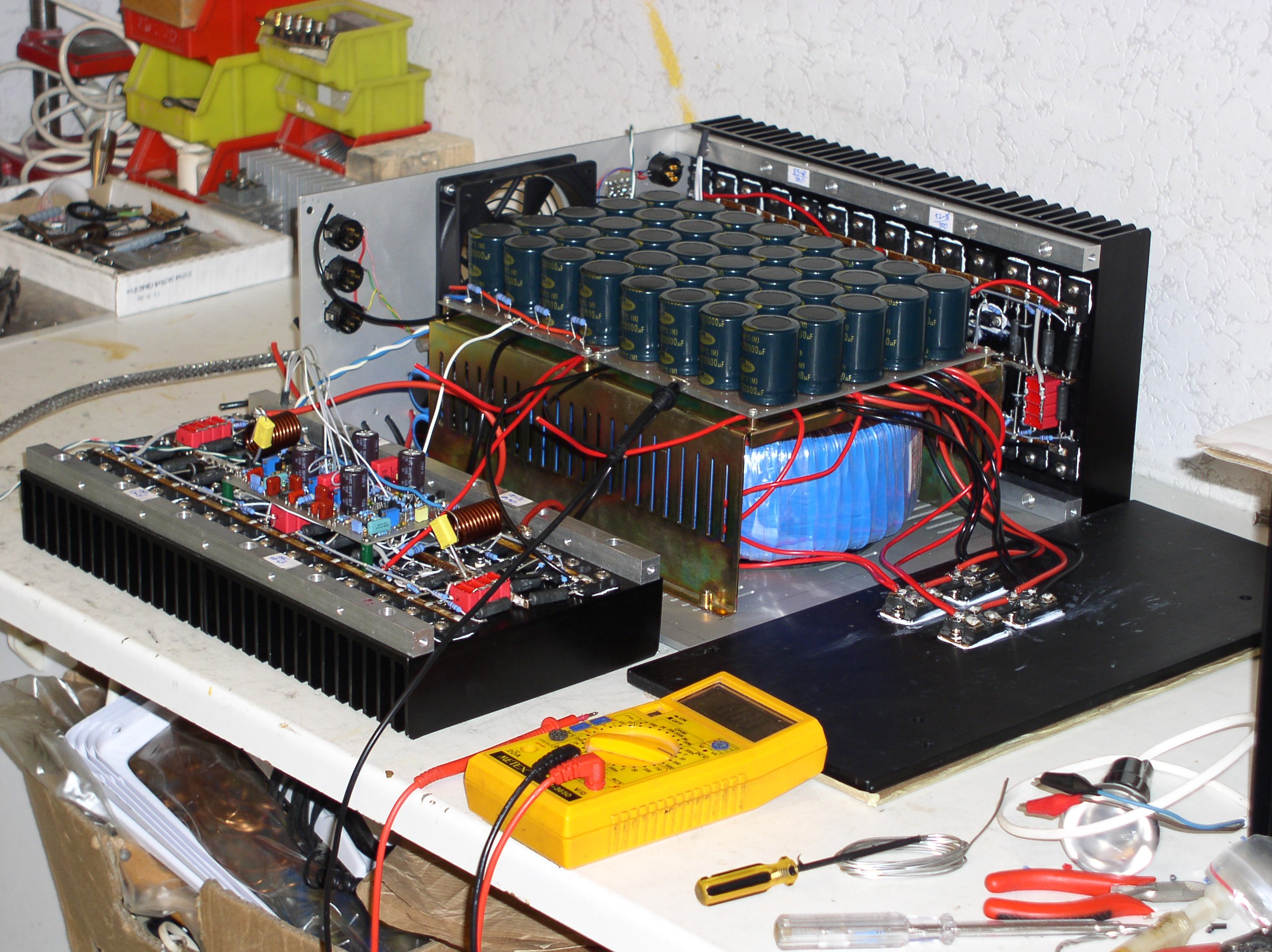
To keep low level of fluctuations and voltage of ripples, energy stored in plus and minus capacitor must be equal to 1/10 of the entire amplifier's power. It is easy to calculate that 4 channels 400W/4ohm each = 1600W. The charge in the capacitor should be 160J for plus and minus, what gives filtering capacity 95.000uF (with the minimum voltage 58V). Due to the compact construction of the device, low profile capacitors batteries Snap-In were used. 40 pieces 22.000uF/35V were connected to create two batteries 110.000uF/70V each.
Quiescent charge accumulated in both capacitors is 400J (for +/-61V).
Two Gratez built on Ixys DSEI 2x101-06A were used.
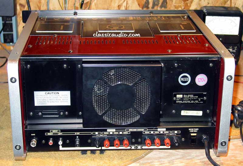
System limiting the inrush current stroke using relay shorts a serial resistor 10ohm/40W after approximately 500ms from power on. 12V auxiliary power supply also powers the fan and relays that power the bridging of pairs of channels. On the rear board of the amplifier, there are control microswitches and fan switch. LEDs in the back indicate active inputs.
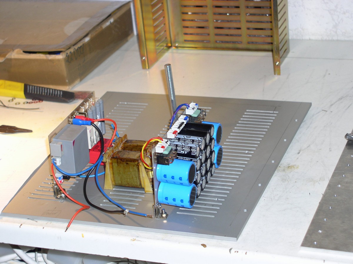
On the left, soft start board, auxiliary transformer and power supply of higher voltage for the voltage part.
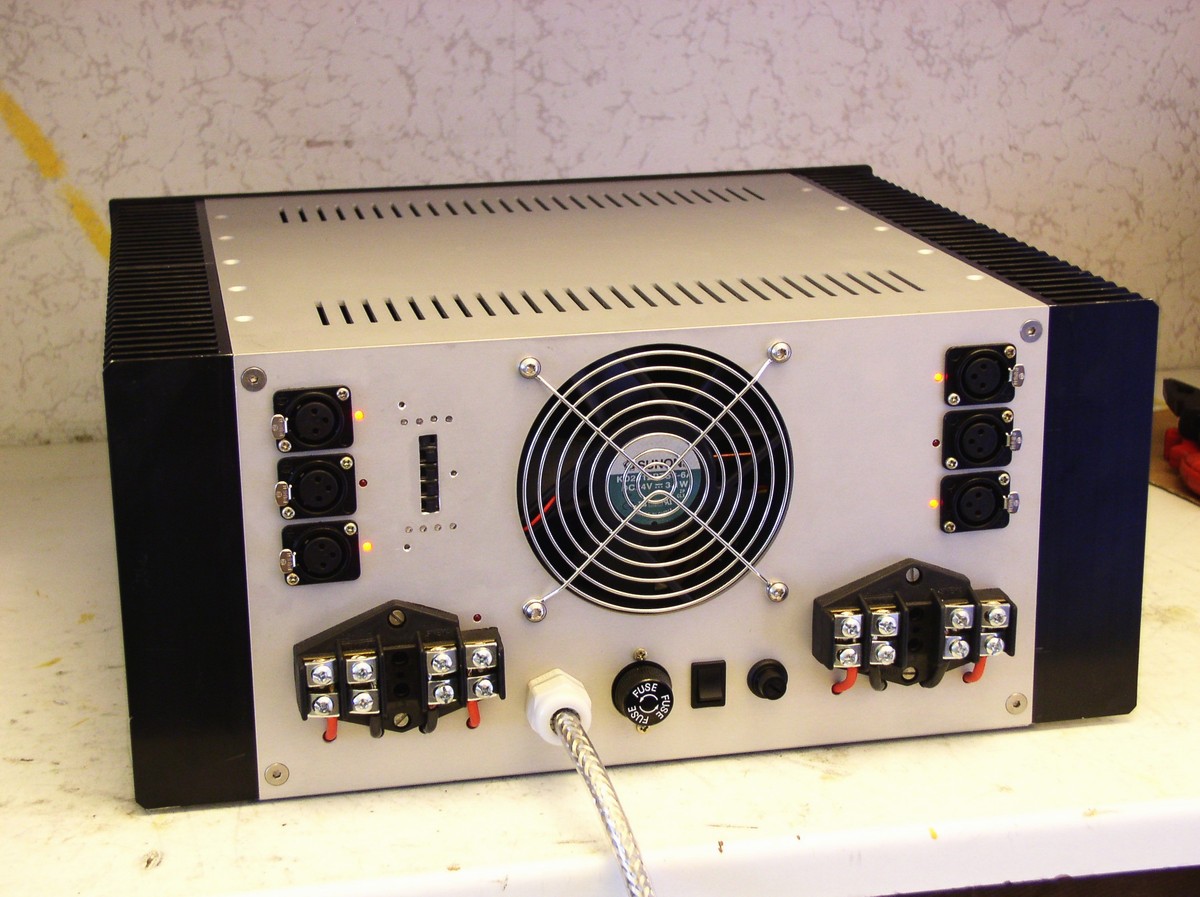
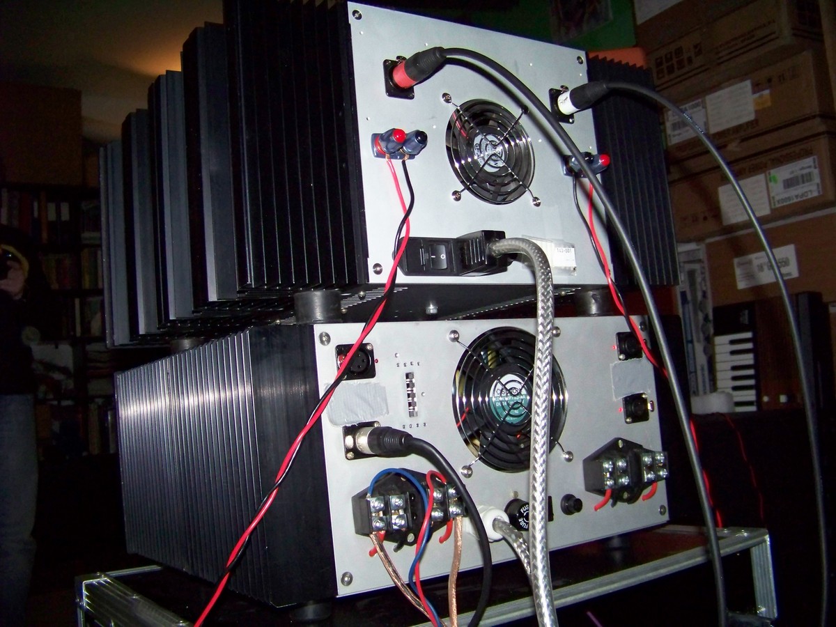
Back and microswitches for configuration control.
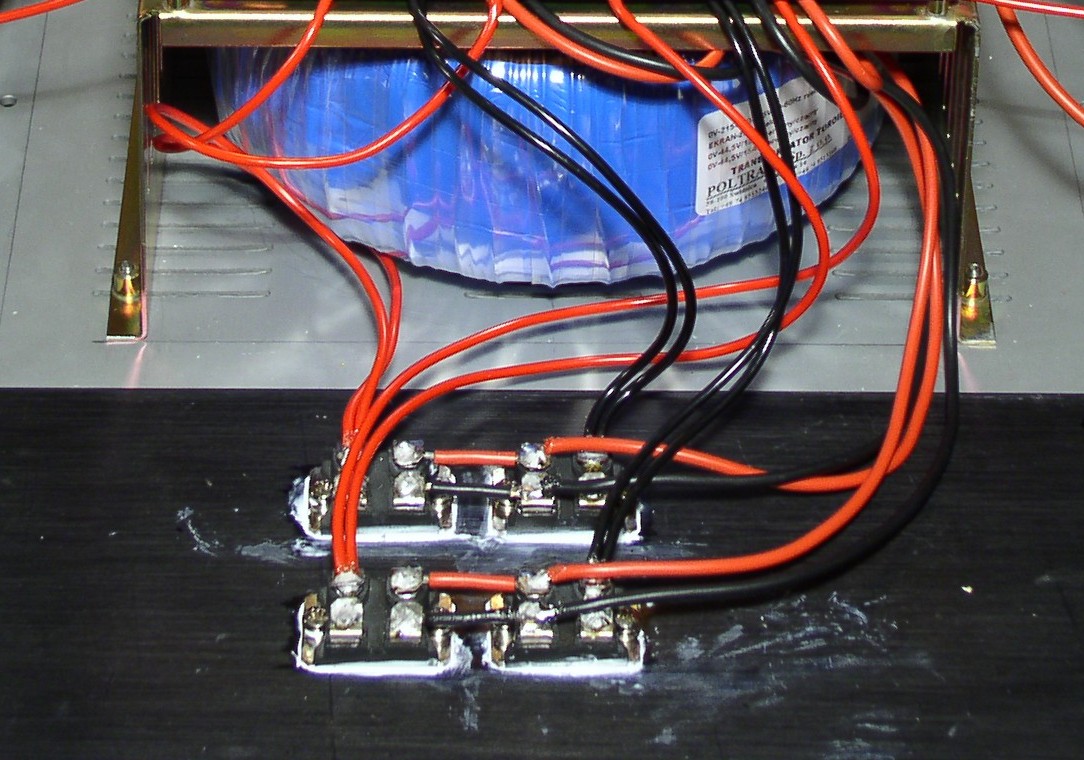
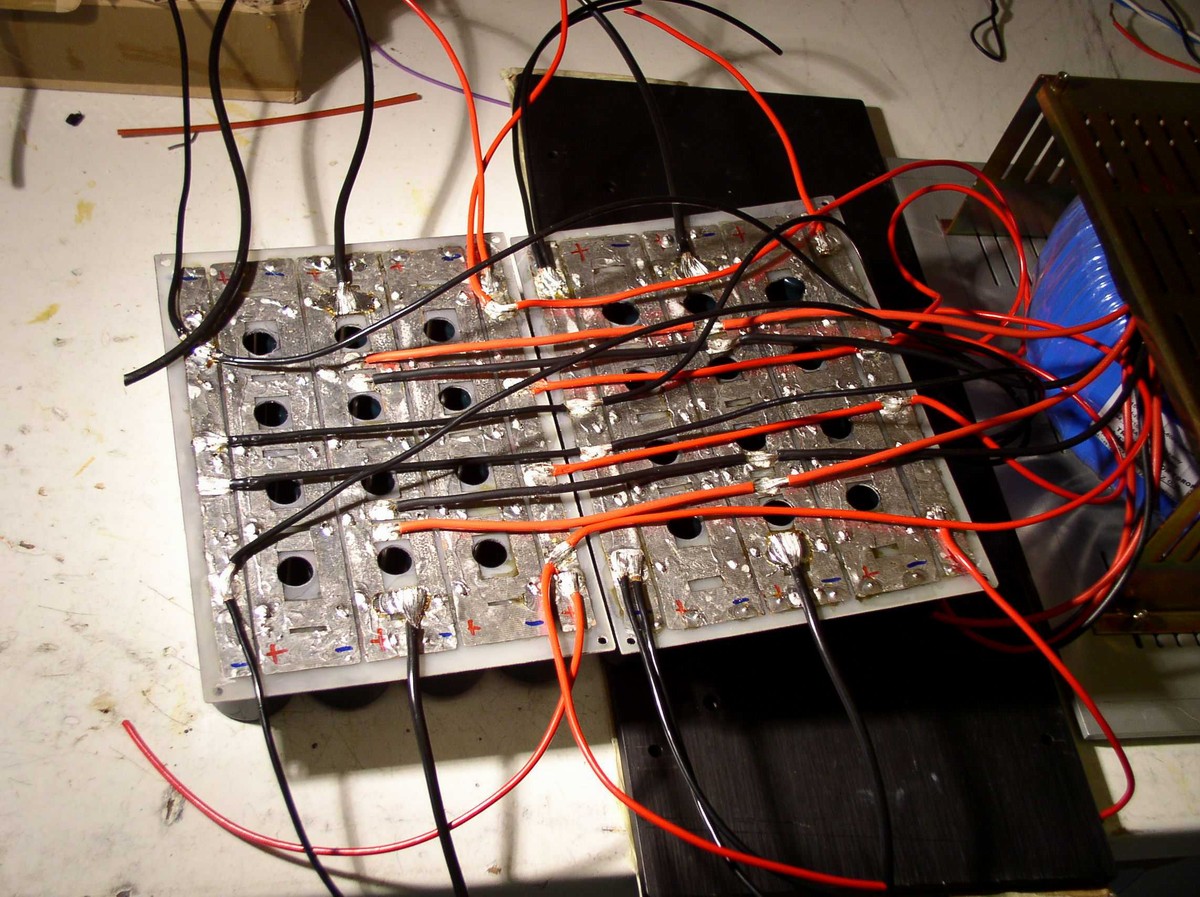
Three 2,5mm2 cables for a + and – bar that provide to the left and right power module, were used for sending such great currents. In the module, collectors are connected by 12mm winding busbar, the same with emitter busbars. Between + and – in three points, capacitors WIMA MKP10 (of 4 pieces of 220nF/250V) were used. An output choke is made of 10 turns on 16mm diameter using 3mm wire. Leads for terminals – 4mm2 cable. Soldering can be in range 160W-200W.

In this project, the main factor causing compression of output power of the amplifier is inner resistance of the mains giving 230V power, because the pulse current on the primary side of the transformer can be up to 30A. RMS is much smaller. During a party, when you use full power, the only protection is an industrial type 4A slow-blow fuse (10x38mm). Remember not to allow for clipping of the amplifier or distortion. Limiter should be set at 1dB before theoretical level of the amplifier clipping. The 1dB is in the event that the mains can drop below 210V.
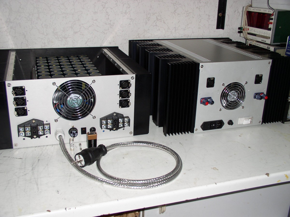
Comparison of the amplifiers' boxes: on the left it is 4x750 with heat dissipation approximately 400W, on the right it is Aleph-X with 800W heat dissipation and a view of the type of safety fuse used 10,3x38mm.

Remember to be very careful while building this device, as it can possibly cause damage to your health (power in capacitors is counted in hundreds of J, what causes risk of dangerous short circuit).
Link to original thread (useful attachment) – Wzmacniacz mocy 4x750W/2Ohm
