Continue to Site

Variable resistor using Microcontroller

Status
Not open for further replies.

Donno191

Newbie level 4
Newbie level 4
Joined
Nov 20, 2010
Messages
6
Helped
0
Reputation
0
Reaction score
0
Trophy points
1,281
Activity points
1,333
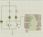
vr.png I Was Wondering if i could build a variable resistor from scratch by using two transistor switches ? If the logic is 0 on PORTA then the power goes through resistor R2 and when the logic is 1 then the power goes through R1. I am more of a programmer than a electronics guy so any help would be helpful my end result is to have a 20bit variable resistor with binary resistance like the first resistor would be 1 ohm, 2 ohm, 4 ohm, 8 ohm, 16 ohm ect and to make 15ohm i would activate the first 4 ports and bypass the last. Hope anyone understands ?
 

hello,

For so low value of resistor 1,2,4..
you cannot use normal transistor, you must use relay ! or FET for value over 100 ohms
for higher value (more > 1K) you can maybe use Analog switch as CD 4066
but what is the context of use for these resistors ?
What voltage accross ? U
maximum current ? I
so power per resistor ?
The best way is tu use relays to have galvanique insulation and no residual ohms with contact...
20 bits variable resistor ? so means 20 relays !
and 1048576 different values possible ?


or use motorised potentiometer 10 turns, with accoupled encoder !
but U ? I ? P ?

you better have to be more precise in your request.
forget your first drawing.
 

Dear Donno
Hi
you can use a transistor as a variable resistor instead of DC signal . but if you want AC signal , you should try Jfets !
Bu before helping you , tell me what you need ( what happened that you decided to do it , ( i predicted some things ) perhaps there are many better ways for your aim .)
Best Wishes
Goldsmith
 

**broken link removed**
this link will tell u how to do that getting good linearity as well
 

hello,

For so low value of resistor 1,2,4..
you cannot use normal transistor, you must use relay ! or FET for value over 100 ohms
for higher value (more > 1K) you can maybe use Analog switch as CD 4066
but what is the context of use for these resistors ?
What voltage accross ? U
maximum current ? I
so power per resistor ?
The best way is tu use relays to have galvanique insulation and no residual ohms with contact...
20 bits variable resistor ? so means 20 relays !
and 1048576 different values possible ?


or use motorised potentiometer 10 turns, with accoupled encoder !
but U ? I ? P ?

you better have to be more precise in your request.
forget your first drawing.
hi the relay idea works good Untitled.png but i am sure there must be beter ways other than relays something smaller ? i don't mind buy whole lot of relays and what would be the best resistors metal film for accuracy ?
Dear Donno
Hi
you can use a transistor as a variable resistor instead of DC signal . but if you want AC signal , you should try Jfets !
Bu before helping you , tell me what you need ( what happened that you decided to do it , ( i predicted some things ) perhaps there are many better ways for your aim .)
Best Wishes
Goldsmith

Hi goldsmith i would like to use it on a broad variety of applications like controlling XR2206 frequency and getting a resonance of an object using a computer XR2206_Function_Generator_Schematic.jpg or if i use a small motor i can use 10w resistors that are controlled via a computer very experimental at this stage.
 

**broken link removed**
this link will tell u how to do that getting good linearity as well

To be honest i am not there with electronics but will keep it in mind for future developments
 

it really WOULD be useful to know how you intend to use these selectable resistors. But without this info, here are some thoughts --

Use a DAC. Don't know about the 20-bit resolution tho'. But explore this possibility.
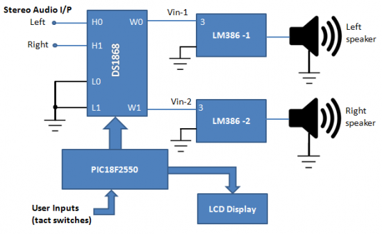
Use digital pots (as suggested above). Again, not sure you'll get 20bits.
 

Digital Potmeters have limited range and only certain values that i why i am thinking of making a DIY one
 

Attachments

  • Digital Potentiometers - Maxim.pdf
    693.1 KB · Views: 499
  • DS2890.pdf
    939.4 KB · Views: 154
  • Industrial 0V to +10V Digital Potentiometer .pdf
    130.4 KB · Views: 221
  • Like
Reactions: dselec

    dselec

    Points: 2
    Helpful Answer Positive Rating
DS2890 Examples

The DS2890 is a linear taper digitally controlled potentiometer with 256 wiper positions. Device operation, including wiper position, is controlled over the single contact 1-Wire bus for the ultimate in electrical Interface simplicity. With a wide 011 volt working voltage range for the potentiometer terminals, the DS2890 is ideal for a broad range of industrial and control applications. Potentiometer terminal voltage is independent of device supply voltage as well as the voltage applied to the other potentiometer terminals.

The DS2890 supports two power modes: a) 1-Wire only mode in which device power is supplied parasitically from the 1-Wire and b) VDD mode where power is supplied from an external supply With a VDD supply the device CAN support both a potentiometer and variable resistor configuration. When operating in a 1-Wire only power mode the device supports only a variable resistor configuration.

**broken link removed**

DS2890-circuits.jpgimages.jpg

Code:
'{$STAMP BS2p}
'{$PBASIC 2.5}

' ----[ Title ]-----------------------------------------------------------
' File...... DS2890.bsp
' Purpose... Using the DS2890 Digital Potentiometer With the BS2p
' Author.... Jared Hoylman
' E-mail.... webmaster(at)jhsys.8k.com
' Started... 23 DEC 2003
' Updated... 24 DEC 2003

' ----[ Program Description ]---------------------------------------------
' This program illustrates how to communicate with the DS2890 digital
' potentiometer.

' ----[ Revision History ]------------------------------------------------
' 24 DEC 2003 - Original Release

' ----[ I/O Definitions ]-------------------------------------------------
OW_Pin  CON 0

' ----[ Constants ]-------------------------------------------------------
WIPERPOS_READ     CON     $F0     ' Read Wiper Pos
WIPERPOS_WRITE    CON     $0F     ' Write Wiper Pos
WIPERPOS_INC      CON     $C3     ' Increment Wiper Pos
WIPERPOS_DEC      CON     $99     ' Decrement Wiper Pos
CONTROLREG_READ   CON     $AA     ' Read Control Register
CONTROLREG_WRITE  CON     $55     ' Write Control Register
ROM_SKIP          CON     $CC     ' Skip ROM Addressing
RESET_NONE        CON     %0000   ' No Reset Pulse
RESET_BEFORE      CON     %0001   ' Reset Pulse Before Data
RESET_AFTER       CON     %0010   ' Reset Pulse After Data
RELEASE           CON     $96     ' Finished

' ----[ Variables ]-------------------------------------------------------
WiperPos          VAR     Byte    ' Used to read/write the Wiper Position
Config            VAR     Byte    ' Used to receive the Config Reg Value
Verify            VAR     Byte    ' Used to verify a write

' ----[ Main Code ]-------------------------------------------------------
Main:

  ' Gradually Increase Wiper to almost max
  DO WHILE WiperPos < 250
    GOSUB IncrementWiperPos
    PAUSE 10
  LOOP

  ' Move wiper between 0 and 250 multiple times
  WiperPos = 0:    GOSUB WriteWiperPos: PAUSE 200
  WiperPos = 250:  GOSUB WriteWiperPos: PAUSE 200
  WiperPos = 0:    GOSUB WriteWiperPos: PAUSE 200
  WiperPos = 250:  GOSUB WriteWiperPos: PAUSE 200
  WiperPos = 0:    GOSUB WriteWiperPos: PAUSE 200
  WiperPos = 250:  GOSUB WriteWiperPos: PAUSE 200
  WiperPos = 0:    GOSUB WriteWiperPos: PAUSE 200
  WiperPos = 250:  GOSUB WriteWiperPos: PAUSE 200
  WiperPos = 0:    GOSUB WriteWiperPos: PAUSE 200
  WiperPos = 250:  GOSUB WriteWiperPos: PAUSE 200

  ' Gradually Decrease Wiper to min
  DO WHILE WiperPos > 0
    GOSUB DecrementWiperPos
    PAUSE 10
  LOOP

  GOTO Main
END


' ----[ Subroutines ]-----------------------------------------------------
ReadWiperPos:
  OWOUT OW_Pin, RESET_BEFORE, [ROM_SKIP, WIPERPOS_READ]
  OWIN  OW_Pin, RESET_AFTER, [Config, WiperPos]
  RETURN

WriteWiperPos:
  OWOUT OW_Pin, RESET_BEFORE, [ROM_SKIP, WIPERPOS_WRITE, WiperPos]
  OWIN  OW_Pin, RESET_NONE, [Verify]
  IF (Verify <> WiperPos) THEN WriteWiperPosError
  OWOUT OW_Pin, RESET_AFTER, [RELEASE]
  RETURN

IncrementWiperPos:
  OWOUT OW_Pin, RESET_BEFORE, [ROM_SKIP, WIPERPOS_INC]
  OWIN  OW_Pin, RESET_AFTER, [WiperPos]
  RETURN

DecrementWiperPos:
  OWOUT OW_Pin, RESET_BEFORE, [ROM_SKIP, WIPERPOS_DEC]
  OWIN  OW_Pin, RESET_AFTER, [WiperPos]
  RETURN

WriteWiperPosError:
  DEBUG "Write Wiper Position Error!", CR
  END


Manually Operated Digital Potentiometer Doesn't Need a Microprocessor
**broken link removed**

**broken link removed**

**broken link removed**
 
Last edited:
  • Like
Reactions: dselec

    dselec

    Points: 2
    Helpful Answer Positive Rating
tpetar,

Hey! I say only in the event of a big emergency!

LOL

Donno191,

If think this can give a hint on your calculations for studying the potentiometer before do it.. It's in Portuguese, but I don't think that it will be hard to understand View attachment Combinaçoes potencias.zip ... I've done some time ago when I was a studying a way to do the variation of power consumption in a generator, for testing purposes, but is similar to the kind of calculations that you will have to do.. so feel free to say if you find any error in the calculations
 
Last edited:

Hi Donno.
Just a thought but resistors in parallel dont have there resistances added together, that is only for series resistances, for parallel resistances you have to do the product of the resistances divided by the sum of the resistance to determine the overall resistance. So dont think the circuit would work as a 20bit variables resistor although it is a nice idea, to do this you would need to have all the resistances in series with each other with a means of bypassing the resistances that you dont want to add to your overall resistance.

Hope this is helpful.

/Pheetuz
 

Pheetuz,

Exactly.. the parallel resulting resistance resistance variation will be logarithmic, but the current will be linear, as long as you choose correctly the resistors... just check the excel file I've posted above
 

The basics of a duty cycle (%d.c.) switched resistance is valid and is used in many areas such as variable loop gain where the switch frequency is well outside the signal band to avoid interference, so Reff=R/[%d.c.] so at 50% Reff= 2R But it is not ideal unless you have a cap to filter the DC current.

There are many types of D to A Converters or DACs such as R-2R ladder switches and logarithmic and sinusoidal DACs. So before you choose something, tell us the design spec or purpose.

35 yrs ago I needed to remote program a bunch of power supplies miles away ... which were R controlled voltages. So I used micro mag-switches with binary R ladder for 8 bit control using a serial link to a desktop calculator with a parallel bus to control the instrument and switched R to control the PS voltage then save the values on mag cartridge for storage of corrected Vdc. ( it was a remote pre-launch rocket controller for scientific research before they put a man on the moon. )
 
Last edited:

Status
Not open for further replies.

Similar threads

Part and Inventory Search

Welcome to EDABoard.com

Sponsor

Back
Top