Continue to Site

Welcome to EDAboard.com

Welcome to our site! EDAboard.com is an international Electronics Discussion Forum focused on EDA software, circuits, schematics, books, theory, papers, asic, pld, 8051, DSP, Network, RF, Analog Design, PCB, Service Manuals... and a whole lot more! To participate you need to register. Registration is free. Click here to register now.

Op-amp saturation continue

Status
Not open for further replies.

mat_lab_trin

Newbie level 3
Newbie level 3
Joined
May 5, 2011
Messages
4
Helped
0
Reputation
0
Reaction score
0
Trophy points
1,281
Visit site
Activity points
1,334
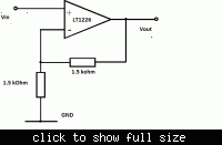
I posted a problem with an op-amp amplification last month and I did not posted enough information.
Now I include the circuit diagram and the result I got.

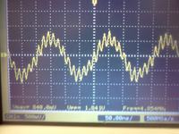
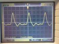
I used LT1226 op-amp with Vss=+10V. the input was the sine wave generate from the function generator (Vp-p = 2V, f = 5MHz, DC offset V=0V).

I connected the output pin to Oscilloscope and I got the result shown in the attached picture.
I want to amplify 20-40mV at 5MHz frequency. If anyone has any suggestion on how to do that, please post it as well. Thank you.
 

Attachments

  • op-amp response.jpg
    op-amp response.jpg
    833 KB · Views: 134
  • op-amp_basic_non_inv.gif
    op-amp_basic_non_inv.gif
    5 KB · Views: 108

Dear mat_lab_trin
Hi
As i saw in it's datasheet , it has GBWP=1MHZ , it means , that at 1MHZ , it's gain will be 0 dB . try to use higher frequency op amps .
Best Wishes
Goldsmith
 

As i saw in it's datasheet , it has GBWP=1MHZ
LT1226 GBW is 1 GHz.

The shown circuit must be expected to fall into self oscillations, because LT1226 can't operate stable at a gain of +2. It's decompensated for a minimal gain of 25, please review the datasheet "compensation" chapter. Apart from this problem, I would appreciate a clear specification of power supply conditions, including bypass capacitors that are essential for a GHZ OP.
 

But i saw that in it's datasheet , wrote these :
GBW.JPG
why the it said , 1MHZ , and in another section it said 1GHZ ? ( i'm a bit confused about it ) .
Thanks
Goldsmith
 

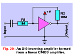
Do you have any CMOS inverter chips or other inverting gates you can use as an analog CMOS amplifier?

Connect feedback resistor R2 out to in. and ac couple with small cap to R1 in , where R2/R1 is gain... Most inverters are 3 stages of x10 gain each so more prop delay than unbuffered series UB but more gain than x10 single stage.. Choose R1 values in 1K~100KΩ for input and 100KΩ ~ 10MΩ range for R2.

Cheap and dirty amp.


I just found a better description of this 40 year old design.

Since CMOS gates are generally used for digital signals, they dont give the Gain x BW product. But you can calculate that from the gain and slew rate. Knowing the linear gain is shown above link and from lab experience. Of course this analog mode uses more current than digital CMOS modes. Back in the 70's we always knew which vendors had faster chips for these modes of use.

Screen shot 2012-04-29 at 6.24.30 PM.PNG
 
Last edited:

I used LT1226 op-amp with Vss=+10V. the input was the sine wave generate from the function generator (Vp-p = 2V, f = 5MHz, DC offset V=0V).
The circuit isn't biased. You are givign the input negative voltage while the output cannot be negative. Thus the limiting effect shown. Make sure you don't exceed the input common mode range, and make sure you don't exceed the output swing capabilities.
 

1GHz G*BW @ 1MHz .. means the device has a 1GHz GBW product @ 1MHz signal, hence G= 1000.

But actually for large signals slew rate limiting takes precedence over GBW product. fortunately this device is rated at 400V/µS whereas a typical 74AHT04 CMOS gate above with 5V@4nS is ≈ 1250 V/µS @ 5V single supply.

whereas your LT1226 needs +/-15V Vss to get this performance. In fact from graphs, a bit less using only+/-5V Vss. but full power bandwidth is FPBW = SR/2πVp

What was your Vss?
 
Last edited:

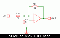
I tested one of the example inverting amplifier with Vss=+/- 15V and Vin = 100mV (p-p). I set the gain at 20 and the response i got is in the attached picture. I don't have any CMOS amplifier. So I have to figure out how to use LT1226. I am not sure whether the op-amp is amplifying Vin or noise. How i can test it?


---------- Post added at 02:22 ---------- Previous post was at 02:11 ----------

I do not really understand about self-oscillating for op-amp. I tried to google the stuff, but didn't find understandable explanation. I tried the example circuit for inverting amplifier with gain of 20 in the data sheet. I used Vss=+/- 15V and Vin = 100mV (p-p). the response of the op-amp is attached to the other reply. The op-amp seemed to gave out correct amplification when I connect Vin to (-) pin of the op-amp. I am not sure whether the amplification is for Vin or noise.

LT1226 GBW is 1 GHz.

The shown circuit must be expected to fall into self oscillations, because LT1226 can't operate stable at a gain of +2. It's decompensated for a minimal gain of 25, please review the datasheet "compensation" chapter. Apart from this problem, I would appreciate a clear specification of power supply conditions, including bypass capacitors that are essential for a GHZ OP.
 

Hi again
I think this problem with a compensation network will solve. use a series RC network in parallel with feed back resistor .
Best Wishes
Goldsmith
 

Op Amps have some phase shift and as FvM already stated, which is clearly up front in the spec....
Features: Gain of 25 Stable that means gain <25 is unstable, which means it tends to oscillate, in your case at 18 Mhz. This is where the conditions for loop gain>1 and phase shift = 360deg. YOur layout must have a good ground plane and decoupled with caps across the supply.

YOu have spurious resonance. Adding filters is a bandaid. YOu need to consider another approach or clean up the spurious response with more phase margin by reducing the bandwidth and increasing the gain to x25 min and eliminate inductive wiring.
 
  • Like
Reactions: FvM

    FvM

    Points: 2
    Helpful Answer Positive Rating
To get a GHz OP operating correctly, some additional requirements need to be observed:
- power supply bypassing, as already mentioned
- low inductance ground. When using bread boards, a RF board with continuous ground plane should be considered.
- feedback networks must be aware of parasitic capacitances and OP input capcitances. Ignoring this point can bring up unstable operation as well.

Using the suggested example circuits from data sheet and layout of evaluation boards provided by the manufacturer is a good starting point.

I do not really understand about self-oscillating for op-amp. I tried to google the stuff, but didn't find understandable explanation. I tried the example circuit for inverting amplifier with gain of 20 in the data sheet. I used Vss=+/- 15V and Vin = 100mV (p-p).

Self-oscillation is just another word for an unstable feedback loop. For the said reasons, there's no G=20 circuit in the datasheet. Apart from the gain number, resistance values and circuit layout matter. You should refer to the literature related to feedback amplifier design, some keywords are "phase margin", "bode diagram","oscillation condition". You'll find many related contributions at edaboard. All analog circuit design text books are discussing the problem.
 

You can improve stability by throwing away some gain. e.g. The circuit below only has a voltage gain of three, but the feedback factor is 0.02, so stability will be the same as a conventional circuit with voltage gain = 50. As an added bonus, the loop gain and stability are independent of whether anything is connected to the input. Doing this will impact the noise performance, though.

 
Last edited:

The device in question is only stable for closed loop gain > 25.
More precisely, it's only stable for feedback factor < 1/25. The circuit above has a feedback factor of 1/50. Another way to look at the circuit is as a resistive divider followed by an amp with a gain of 50.

I agree that a CMOS inverter would be workable too, but doesn't that introduce more unknowns? Presumably they can oscillate too, depending on the closed loop gain and impedances used. At least with an opamp, the datasheet gives the relevant information regarding stability criteria.
 
Last edited:

Status
Not open for further replies.

Part and Inventory Search

Welcome to EDABoard.com

Sponsor

Back
Top