Continue to Site

Welcome to EDAboard.com

Welcome to our site! EDAboard.com is an international Electronics Discussion Forum focused on EDA software, circuits, schematics, books, theory, papers, asic, pld, 8051, DSP, Network, RF, Analog Design, PCB, Service Manuals... and a whole lot more! To participate you need to register. Registration is free. Click here to register now.

cant use lm723 voltage regulator

Status
Not open for further replies.

anonymous.

Junior Member level 3
Joined
Apr 16, 2012
Messages
27
Helped
0
Reputation
0
Reaction score
0
Trophy points
1,281
Visit site
Activity points
1,485
hi guys,

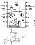
i want to make a power supply using LM723 but i cant understand how to use it. I dont know what the pin functions are (current limit , current sense , Vz , .....)
can anyone tell me how to use this IC ?? or any online tutorial .


thanks.
 

CA723 Type voltage regulator can be used for regulated output voltage from 2V to 37 V at output current upto 150mA without external pass transistor

---------- Post added at 22:47 ---------- Previous post was at 22:40 ----------

This is the pinout


---------- Post added at 22:50 ---------- Previous post was at 22:47 ----------

And for the application part, what voltage and current you need
 
hi guys,

i want to make a power supply using LM723 but i cant understand how to use it. I dont know what the pin functions are (current limit , current sense , Vz , .....)
can anyone tell me how to use this IC ?? or any online tutorial .


thanks.
first build it and after it works well help
Google "lm723 voltage regulator circuit"
New Bitmap Image.GIF
 
Last edited:
And for the application part, what voltage and current you need

a 2-30 volts variable
no current amplification
150mA
i just want to understand how it works so i can design one myself


Google "lm723 voltage regulator circuit"
View attachment 73076

searching google about this gives back many complicated circuits that are way to hard to understand

anyway in this simple examle that u included
why are the(Vout , Cl , Cs , comp , inv) connected that way ??
 

Its not easy
what is your background in electronics ?
U will have to read the 723 data sheet first for u to understand our explanation.
in general vc v+ pass the vin+ to vo vz
inv gets info about output and adjust the circuit auto so output is stable
nin 5 decide what output u want

google "how does voltage regulator work"
https://www.ece.cmu.edu/~ee100/docs/Chapter5.pdf
 
Last edited:

not a good background
some readings here and there !!

i can understand from the circuit you provided that the voltage reference is amplified and outputed on Vref pin
then with a voltage divider input can be taken on the non inverting pin

connecting the frequency compensation and inverting pins this way makes the op amp integrator
I cant see why

the transistor on Vout and Vc is mostly used to amplify the output current


as for the other components(the zener,other transistor) i dont know about them


I have just seen the datasheet
gives the equivalent circuit you included with some examples
still cant get what i missed
 

https://www.electronics-tutorials.ws/
u need to learn all the basics start doing that at the link above.
u need to know how atransistor works in this matter the current passes from cc to vo depending on the error amp.
the error amp compares the wanted voltage to the real voltage and so the amp feed the transistor until there is a balance holding it allwayes in balance.
 
connecting the frequency compensation and inverting pins this way makes the op amp integrator
I cant see why
The capacitor connected between those pins is for high-frequency stability, to prevent the circuit from oscillating.
 
Status
Not open for further replies.

Part and Inventory Search

Welcome to EDABoard.com

Sponsor

Back
Top