Continue to Site

Welcome to EDAboard.com

Welcome to our site! EDAboard.com is an international Electronics Discussion Forum focused on EDA software, circuits, schematics, books, theory, papers, asic, pld, 8051, DSP, Network, RF, Analog Design, PCB, Service Manuals... and a whole lot more! To participate you need to register. Registration is free. Click here to register now.

AC Electronic Load Schematic

Status
Not open for further replies.

cooldesire

Newbie level 4
Newbie level 4
Joined
Dec 21, 2010
Messages
7
Helped
0
Reputation
0
Reaction score
0
Trophy points
1,281
Activity points
1,331
Hello all, anyone can help me for "AC electronic load circuit" or any advice, idea
ratings: Min. 48V-1A, 48W
it is very important, this is my final year project
 

Find the article on a simple electronic load here:
https://www.google.com/#hl=en&gs_nf....,cf.osb&fp=3b2e19c71d66c793&biw=1680&bih=882
You will have to download the pdf version of the article to see the schematic.
This is a DC load. For AC operation, the simplest solution is to put a bridge rectifier in front of it, with a filter capacitor following the bridge. You can ignore the voltage regulating part of the circuit and the relay.
Vref will set the constant current level. you will need to arange for a power supply for the IC.
A possible modification is to use two MOSFETs in series, with the gates tied together and the sources tied together. The two drains connect to the input terminals. MOSFETS connected like this will work on AC,
with each MOSFET caring the load on alternating polarity of the input.
You will need to do some bench work to finalize this design.
 
In this way, can I shrink ac current from the tested load after the bridge rectification?
thanks a lot for your helps
 

I assume you want to simulate a purely resistive load?

A bridge rectifier on the output will make designing the load easier, though it will introduce some zero crossing distortion into the load current.

After the rectifier you'll want a voltage controlled current sink, which is controlled directly from the rectified AC voltage. The gain (transconductance, if you want to call it that) of the current source is what you adjust to change the "resistance" of the active load.
 

"ntwieg",your assume is correct. Allright, how can I design a voltage controlled current sink
for this circuit...
:( There are many things I do not know

---------- Post added at 13:53 ---------- Previous post was at 13:39 ----------

"MOHA45", these two mosfets both of them N-channel or what...
I will prepare the circuit for the simulation now
 

"ntwieg",your assume is correct. Allright, how can I design a voltage controlled current sink
for this circuit...
:( There are many things I do not know

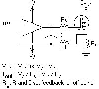
A current sink is pretty simple to make with an op amp and transistor:
53_1335534314.png


The control voltage is fed to the op amp, and the sink current should be Vin/Rs. So if you feed your rectified sine wave to Vin (with some attenuation), then the current sink will just appear as a resistor. But by varying the attenuation between the AC source and the current source input (with a potentiometer), you can effectively change that resistance.
 

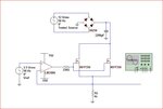
curcuit1.JPG
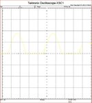
osi.JPG
above the simple circuit and simulation result I made, according to your suggestions
but I have problem, I want to full sinusoid voltage across the Rs resistor,
from the osiloscope result Vs seems to half-wave sinusoid(in the above attachments)...
how can I overcome this problem...

I am obliged to you, for your helps...
 

That's because in your simulation, the control signal is an unrectified AC signal, and the current sink can only work in one polarity. What you should do is use the output of the bridge rectifier as the control signal (after attenuating it with a resistor divider). Also the capacitor on the rectifier output isn't needed, and will only distort the load current seen from the AC source.
 
Post #7 reveals that there's some confusion involved with your problem specification.

The sine generator and "sine wave across Rs" requirements suggests a bipolar current source. But how do you want to generate a bipolar current with an unipolar (bridge rectifier) voltage supply? It's also not exactly clear, if you're intending a passive or active current source.

My suggestion is to sketch a typical test circuit using the intended current source, with the source as a black box, just to clarify it's properties. Some related thought can be found in this thread https://www.edaboard.com/threads/247991/
 

I think, all the problem is rectification of the tested ac source
we need to revise all circuit with a non-rectification circuit
because after rectification we can't achieve sinosoidal voltage across the Rs resistor

I would like to remind that "My target is while testing the ac source in purely resitive mode, I want to shrink ac current from the source"
Schematics explanations are more clear and more understandable for me...
 

Schematics explanations are more clear and more understandable for me...
For me, too. That's why I asked you to show a schematic that defines the project problem more clearly than your words.
 
If things continue to happen like this, I'll fail the course... please help me... :(
I just want to simple schematic...
 

I tend to read post #11 as describing an active bipolar current source driving a passive load, assumed resistive. We apperently agree that words are often not so clear.

If my guess is right, the discussion in the said thread https://www.edaboard.com/threads/247991/ exactly apllies to your problem:

You need a bipolar current source, powered by a bipolar supply. Using a linear voltage amplifier with current feedback is one of several possible options. Another option would be a combination of two complementary unipolar sources.

Or it's the other way around, you are desribing an electronic load? In this case, the intended behaviour should be specified more clearly first. Behaving as a resistor implies, that the current through the load is defined by the applied voltage, not an independent generator. A "simulated" resistance would be the only parameter, that can be set for a resistive load.
 
Last edited:

Status
Not open for further replies.

Similar threads

Part and Inventory Search

Welcome to EDABoard.com

Sponsor

Back
Top