TriggerHappy
Junior Member level 3

I want to partially shield bluetooth antennas so that their ranges are reduced. My motive is that I want to use reception or non-reception as a means of measuring indoor location (of my mobile phone with simple software for that purpose) with a room by room resolution. Bluetooth is by standard far too powerful for that, easily penetrating walls and floors.
Here is an image of a bluetooth hands free device opened:
https://imageshack.us/photo/my-images/267/bt95switchlarge.jpg/
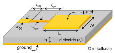
I suppose that the zigzag pattern to the left (about 12mm by 4 mm) is a bluetooth patch antenna.
QUESTIONS:
1) Roughly how are the radio waves propagated from such an antenna (2.4 GHz)? For example, stronger in its plane or perpendicular to it? On the bottom side of such patch antennas, I've read that there should be a ground plane. Does that mean that it doesn't transmit at all directly through that plane? (Reception in that direction would then be explained by reflections)
2) Is it feasible, as imagine, that it suffice to gradually cover it with metal until the range is optimal. I imagine for example twining thin insulated wires around it. 1-4 rounds would gradually cover it and provide sufficient degrees of range choice. Or covering it completely on three sides, and cutting partially covering aluminium foil patterns to stick onto its front with some adhesive. (I'm on a low budget concept testing level).
3) Would there be any better way to reduce signal strength than to partially shield the antenna? I have no real documentation about the bluetooth chip, but the signal strength seems to be very low level hard coded. And breaking the commercially mass produced standards could require very expensive new chip development. Or is there a short cut?
I have achieved optimal range by covering the entire device with steel wool in even and measured thickness. But it is flimsy, and I want to get up close to the antenna itself now, in hope of making range adjustments tidy, sturdy and repeatable with precision.
(And any feed back on my project idea as a whole is always very welcome!)


