Continue to Site

Welcome to EDAboard.com

Welcome to our site! EDAboard.com is an international Electronics Discussion Forum focused on EDA software, circuits, schematics, books, theory, papers, asic, pld, 8051, DSP, Network, RF, Analog Design, PCB, Service Manuals... and a whole lot more! To participate you need to register. Registration is free. Click here to register now.

single phase inverter shcematic

Status
Not open for further replies.

nxt_

Member level 4
Member level 4
Joined
Aug 16, 2010
Messages
69
Helped
4
Reputation
8
Reaction score
4
Trophy points
1,288
Location
Egypt
Visit site
Activity points
1,834
Dear Engineers,
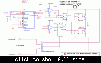
Kindly could any one check the attached schematic for single phase dc to ac inverter and tell me if it okay to drive with this circuit a 220v 75 watt ac motor. and if is not. what should i add to the i/p to the transformer to ensure soft starting.

Many Thanks For Your Attention.
Regards.


---------- Post added at 02:02 ---------- Previous post was at 02:01 ----------

i know that the circuit power capacity is about 500watt but i want to know if it is efficient or not.
 

Connections of lower side drive are wrongly connected. It should be like of upper side. Collectors of all four transistors are connected together and are connected to one side of transformer winding.Similar should be for other side. Bases of two power transistors go to emitter of driver transistor. Although it will work but it is not efficient. Transistors will run hot.
R2 is frequency determining component . For 50 or 60 Hz its value is around 100K. Consult datasheet to calculate for values for C and R according to your requirement. 100 ohm is very low a value.
 
  • Like
Reactions: nxt_

    nxt_

    Points: 2
    Helpful Answer Positive Rating
Dear ALERTLINKS
could you please tell me more about what you think of this circuit. why the schematic is wrong?
 

Base and emitters of the lower output transistors are shorted together!

I'm sure that's just a drawing error but the circuit is not particularly good. It has poor frequency stability, no voltage regulation and produces a square wave drive signal to the transformer. The two op-amps do nothing useful, you could omit them altogether. It will work but not very efficiently.

Brian.
 
  • Like
Reactions: nxt_

    nxt_

    Points: 2
    Helpful Answer Positive Rating
i am searching for the simplest single phase inverter and acceptable efficiency :S
 
First you must tell us what type of load you will be driving. The schematic you gave will drive a square wave into the transformer which is both inefficient in terms of power conversion and also because the output waveform will be highly distorted it will not properly drive inductive loads such as motors.

If the output waveform is not critical, a simple modified sine wave circuit will work far better than a square wave one. If you want a clean sine wave output there are two options, a sine oscillator, high current driver and a step-up transformer (very inefficient) or a PWM bridge driver (complicated and more expensive but efficient).

Brian.
 
  • Like
Reactions: nxt_

    nxt_

    Points: 2
    Helpful Answer Positive Rating
betwixt.many thanks for your attention. i made pic18f452 based single phase full bridge inverter with igbt 60n90. switching frequency 5khz (maximum frequency for 4n35 optocoupler ) i'll post the schematic soon . i am confused about two point the filtering stage! and the load limitations. and how to synchronise between load (inductive or resistive) ,the switching frequency and duty. so please after posting the schematic looking forward to clarify for me these two points and i'll be grateful.

Thanks.
 

Status
Not open for further replies.

Part and Inventory Search

Welcome to EDABoard.com

Sponsor

Back
Top