bmandl
Full Member level 4

- Joined
- Feb 26, 2010
- Messages
- 210
- Helped
- 3
- Reputation
- 6
- Reaction score
- 3
- Trophy points
- 1,298
- Location
- Slovenia
- Activity points
- 3,006
Hello!
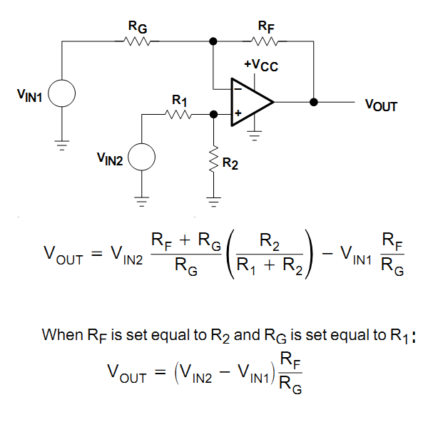
It's been a long time, since I last time posted on this forum. And here I am with a problem. I have build myself an v-a meter. V-meter works great, now a-meter it's causing me some trouble. It is like that. I am using LM358 as differential amplifier for current sensing. My calculations are, that I should get approx. 8V on the output of amplifier at 1.41 V of input (3A through 0.47R shunt resistor). But I am getting just 1.43V, same as the input. I also noticed, that I get 1.41V on - input of amplifier, instead of 0V. Can someone at least give me a clue of figuring out my problem, please. Below it's schematic file. One note: I am supplying amplifier with 15V DC, not 5V as it is on schematic.
It's been a long time, since I last time posted on this forum. And here I am with a problem. I have build myself an v-a meter. V-meter works great, now a-meter it's causing me some trouble. It is like that. I am using LM358 as differential amplifier for current sensing. My calculations are, that I should get approx. 8V on the output of amplifier at 1.41 V of input (3A through 0.47R shunt resistor). But I am getting just 1.43V, same as the input. I also noticed, that I get 1.41V on - input of amplifier, instead of 0V. Can someone at least give me a clue of figuring out my problem, please. Below it's schematic file. One note: I am supplying amplifier with 15V DC, not 5V as it is on schematic.


