Continue to Site

Welcome to EDAboard.com

Welcome to our site! EDAboard.com is an international Electronics Discussion Forum focused on EDA software, circuits, schematics, books, theory, papers, asic, pld, 8051, DSP, Network, RF, Analog Design, PCB, Service Manuals... and a whole lot more! To participate you need to register. Registration is free. Click here to register now.

[SOLVED] sine wave oscillator 1KHZ

Status
Not open for further replies.

nima_1981

Member level 3
Member level 3
Joined
Apr 22, 2010
Messages
61
Helped
0
Reputation
0
Reaction score
0
Trophy points
1,286
Location
Ocean Mind
Visit site
Activity points
1,877
Hi Every Body ,
I Should say sorry for my English writing at the first .
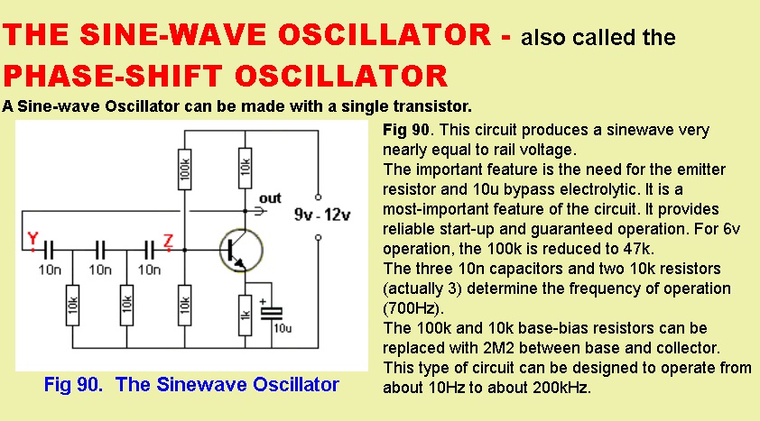
i found this Circuit for generate sin wave .
osnew.jpg

but what is my problem
i simulated that in proteus (Isis)
1) i can not fix Frequency In 1 Khz i can not find how i can change frequency
2) also i can not get negative Voltage for this Wave when i connect positive and negative supply .
thanks
this is download link for simulated circuit
**broken link removed**
 

Hello my friend
At first step you should know that , that circuit called phase shift oscillator . the out put of CE amplifier is out of phase , with 3 section ( RC networks) we can create 180 degree pahse shift for neutralizing the pahse . and thus we have a positive fed . and about oscillation : we have a law of oscillation : feed back ratio * Gain should become one or greater than one . because vi=0 ......> Vo= AV*Vi/1-beta*AV thus if beta* AV become one , the equation will be 0/0 and the circuit can do oscillating .
By the way , about simulation : many of oscillators , need instantaneous value to provide oscillations . use Ic probe or transient keys .
Best Wishes
Goldsmith
 
thanks
but another thing what is u1 and u2 in your schematic ?

---------- Post added at 18:45 ---------- Previous post was at 18:41 ----------

And about formula of oscillations: F= 1/(2*pi*R*C* 6 unedr radical )

Dear goldsmith My compatriot
the R and C is which one in your schematic ?
 

Dear Nima
My mean by R and C , was C1 and C2 And C3 and R4 and R5 and R6 ( remember , that at AC equivalent circuit , the RC ( collector resistor ) is from collector to ground ) .
And about u1 and u2 , in fact nothing special . those are for transient shock . ( unit step).
Good luck
Goldsmith

---------- Post added at 21:47 ---------- Previous post was at 21:20 ----------

By the way , you'de better to set your input impedance , equal with R.
 
dear GOLDSMITH
why ground contented to negative voltage in your schematic ?
is this right i should connect ground between positive and negative voltage ?
 

Dear Nima
do you know meaning of ground in each circuit? it is a reference point . the ground can be considered negative or positive . it depends on your standards. but currently , the standards is that , the ground , is considered , the negative of supply . ( the current wants flow from positive to ground , but in fact it is not correct , but it is a law .)
Wish you the best
Goldsmith
 
Last edited:
Dear Goldsmith
I assembled your circuit on bred board i have this on my oscilloscope
but i can not fix frequency on 1 khz by change r4 r5 r6 or c1 or c2 or c3
can you help me for fix frequency on 1k Hz


**broken link removed**
 
Last edited:

......but i can not fix frequency on 1 khz by change r4 r5 r6 or c1 or c2 or c3
can you help me for fix frequency on 1k Hz

I can see f=318Hz --> replace C1,C2,C3 by others ~3 times smaller. (if 10n --> 3n3) and replace R6 by a ~10k preset or trimpot.

After that, the frequency should be near 1Kz. Then make a fine adjust with the preset.
 
I can see f=318Hz --> replace C1,C2,C3 by others ~3 times smaller. (if 10n --> 3n3) and replace R6 by a ~10k preset or trimpot.

After that, the frequency should be near 1Kz. Then make a fine adjust with the preset.
thank you _eduardo_
Now i have a near 1 khz
But why my amplitude is decrease to 2 Volt i need 8 Volt !!
do you have any solution for this ?
 

To increase the amplitude you must modify the polarization of the transistor. This adjustment is best done using the oscilloscope to minimize the distortion.

Anyway, that circuit is basic, because frequency and amplitude are load dependant --> you must add an output stage, and do the adjustment of amplitude and offset at this stage.


Shakespeare: I'm sorry.
 
Status
Not open for further replies.

Similar threads

Part and Inventory Search

Welcome to EDABoard.com

Sponsor

Back
Top