Continue to Site

Welcome to EDAboard.com

Welcome to our site! EDAboard.com is an international Electronics Discussion Forum focused on EDA software, circuits, schematics, books, theory, papers, asic, pld, 8051, DSP, Network, RF, Analog Design, PCB, Service Manuals... and a whole lot more! To participate you need to register. Registration is free. Click here to register now.

Need help on high side driver

Status
Not open for further replies.

kanonka

Member level 1
Member level 1
Joined
Dec 12, 2011
Messages
35
Helped
0
Reputation
0
Reaction score
0
Trophy points
1,286
Activity points
1,760
I know this question was beat up to death :), but stay with me for a second.

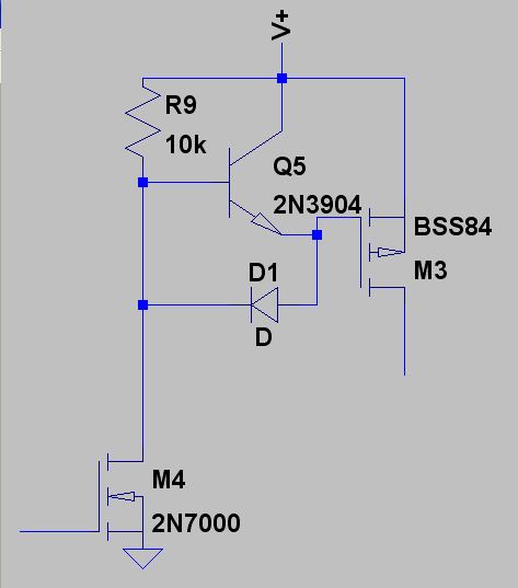
In short, I needed +/- 5V and +/-10V (well, can go as low as 8) rails coming from a 3.7V battery with the highest efficiency possible. The big caveat - power supply cannot have any inductors in it (well, at least no more than 10-20 nanoH) due to low-field sensing magnetic sensors right next to it. So I looked at the charge pumps. None currently on a market suited me because for the battery full life voltage range (2.8V .. 4.25V from charge to discharge) they had efficiency after LDO less than 50%. Making long story short, I managed to come up with an idea (already successfully simulated it in LTSpice) that solves the task with an average efficiency of 91% (I expect real life numbers to be around 86-88%). But here comes a big BUT. The application is portable, so I'm VERY limited in space - all in all I have about 400-450 sq. mm for the pump charge alone. Problem is, it has about 30 MOSFETs, 20 of them being high-side, that I need somehow to drive. The time I need to turn one mosfet on or off is limited by 5microsec - can't have any longer as caps are getting too big to fit my limited space. First I started off with N-FETs, but existing drivers either require way more than my minimum of 2.8V, or are very slow (like LTC1982 - 110us to switch!). Also, using monolitic charge pump to drive my own charge pump looks like a stupid idea :), so I looked at the option to use P-FETs on a high side. Situation became better here, but not by much. I still can't find reasonably-sized P-FET driver (2x2mm or less) working from minimum 2.8V. Also, source of half P-FETs 50% of the time is taken much higher than V+ rail, so the only option I have left is a well-known discrete driver (you know, one low-power N-FET + 3 resistors). The problem I have with this approach is that it is a discrete (3 resistors * 20 P-FETs = 60!!! It will take years to put them onto PCB while soldering :( ), and also I don't know how to discharge gate fast (I suspect, it will require even more components).

So, finally, here is a question: does anyone know a monolitic high-side P-FET driver that:
1) can run from as low as 2.8V and
2) connects to gate AND source of the P-FET to allow source be above the rail (ANY rail in the system - this is important) - something like IRS2112 and
3) be small enough (preferably 2x2mm or less; max I can have is 3x3mm, but even that is too much; unless it incorporates 2 or more channels) and
4) require no or bare minimum external components.

I searched high and low for couple weeks now and can't find one. Any advice? Or may be I should totally change a design of the power supply?
 

The simplest fast PMOS driver circuit I know of is this:


But that probably requires too many components for you, and I highly doubt you'll find something like that in a monolithic package. It sounds like you need a custom ASIC.

Just so you know, there are ways to use chokes in applications that are extremely sensitive to magnetic fields (I should know, I work on MRI hardware). Properly shielded toroidal inductors tend to give stray fields almost as low as a simple piece of wire. I wouldn't write off the idea completely.
 

The simplest fast PMOS driver circuit I know of is this:
Hmm. Good idea, I'll look into it if I could simplify or may be combine few ones - thanks for the input!
Just so you know, there are ways to use chokes in applications that are extremely sensitive to magnetic fields (I should know, I work on MRI hardware). Properly shielded toroidal inductors tend to give stray fields almost as low as a simple piece of wire. I wouldn't write off the idea completely.

Can you elaborate on this? How can I find the stray field strength for an inductor from the datasheet? Or may be you recommend one? From what I see, any inductor of 2uH to 10uH will be enough to drive my power supply, given that at 20mm distance stray field does not exceed 5-10uGa.
 

Can you elaborate on this? How can I find the stray field strength for an inductor from the datasheet? Or may be you recommend one? From what I see, any inductor of 2uH to 10uH will be enough to drive my power supply, given that at 20mm distance stray field does not exceed 5-10uGa.
It certainly won't be given by the manufacturer; you'd have to use a field simulator program. Coming up with good solutions can be a very rigorous process, but being able to use permeable materials helps a lot (we can't inside the scanner since everything would saturate in there...).

But I think you may have a problem, because 5-10uGa is so small that even the current coming from a few mA of current, with no inductor, will far more than that much error. For example, 10mA flowing through a wire produces a field of 100nT, or 1mGa, at a distance of 20mm. Careful control of return currents can help, but I don't know if 10uGa is feasible under any circumstances at that distance (again, unless you have an ASIC, where the size of current loops are kept very tiny and produce very small fields).

Yes, that what I figured. The application design is so that I don't care much about steady currents (like power ones) because they all will add up to initial offset and be compensated; besides all my traces where current/voltage alternates are either signal ones (with currents less than tens of microamperes) or very short ones (less than 3mm). But any big alternating currents are of a big concern, and however shielded inductor will posses a problem. Charge pump also produces big currents (of up to 0.8A magnitues), but I sync measurements to a moments when cp current is almost off. Very tough taks by itself :(, even though it looks simple -I don't need to monitor slew rate and other things - simple clock divider at MCU + rise front of a cycle does the job, but adding inductor will complicate things much further.

P.S. I must add that design of ultra-low noise applications in a limited space is a nightmare of compromises :(.
 

Well synchronizing the measurement with the converter operation is a nice idea, and there's no reason you can't apply that to a inductor-based DC-DC converter. If you restrict the converter to operate in discontinuous mode, then you can do your measurements during the dead time.

What kind of fields are you trying to measure, and what is your transducer? I assumed it was a low-frequency detector, but it seems that's not the case.

Well, I'm very new to power design, so I'm not fully familiar with all the cycles of an inductor-based DC-DC converter, but I got an impression from the complexity of corresponding controllers that it would be almost impossible to sync with them. Either they are a low freq (so I can sync), but big inductor(s), where current is not settled enough for quite some time, or high freq with small inductors, but I can't sync with them, as minimum measure time is 1.5us, and I need at least 2 measurements taken in between of cycles. With 10-20 kHz charge pump single control impulse is 20-40us, and currents are almost stable for about 4-8us, so I can fit my measurements in. I donno if I can achieve that wih an inductor, as current there even after 5 tau time multiplied by permeability gives magnetic fields way higher than comparable current in a simple wire as in case of charge pump.

I'm trying to measure fields of 0.07-0.1Ga with precision of at least 0.1%, which means any fast oscillating field over 25uGa is an obstacle. My sensors are HMC1021, but I also want to try HMC1043, although datasheet gives 3 times worse performance on a resolution - but who knows, conditions for what these numbers are specified are different from mine (they quote noise and resolution over 0.1 - 10Hz band, which is not my case), so it might work. Right now I'm doing a prototype :), so whole idea might be wrong, but I hope for the opposite :)

The process is - measure field, consider it a zero, fire up magnet, in a 0.5ms measure field again (quite a few measurements on many sensors), take the difference, stop the magnet. Repeat :)
Okay, I have experience with the HMC sensors so I understand the challenge a bit better. I assume you're using the "chopped" measurement method where you take measurements after each set/reset pulse and take the difference to eliminate offsets.

What you want to do is tailor your measurement method to require as little bandwidth as possible. If you can get it down low enough, then you can just filter off high frequency signals in the analog domain, and not worry about high frequency interference. Do you really need to do a pair of measurements a few us apart? Do you really need to switch your "magnet" (not sure what you meant there) every 0.5ms?

Yes and yes to both last questions. If I could do faster measurement, I'd like to do so, but so far I'm settled with AD7984/AD7982. My one total measurement period is 1ms. In this timeframe I have to:
a) fire up a magnet (whose field sensors will be measuring) and wait 7 tau to have it settle. Due to some external restrictions (which I have no power over) I cannot make this time less than 0.5ms, so I have left 500us for everything else;
b) then I need to make measurement from 24 sensors. AD7984 specified for 1us, but taking time for muxes and MCU I expect total measurement time for one sensor to be 1.5us. I'd use multi-channel ADC, but then I'd have to use more amplifiers etc, and I'm limited on a power and a board size (honestly, I'm thinking right now to fit everything onto two PCBs of the same size and sandwich them together - otherwise I already have no idea how to fit that many components in my space). So, trailing on a stabilized periods of a converter, I have 2 measurements every 20us, so for 24 measurements I need 240us.This leaves 260 us for everything else.
c) I need to spare at least 60us for the "big cycle" run every 10ms - to take "zero" measurements. So this leaves 200 us for the rest.
d) Somehow I need to fit into these 200us somewhat simple MCU calculations AND data transmission to another MCU via RF. I don't think I can do that - so I should fit some data transmission into next 0.5ms when magnet starts new cycle.

So, simple task of periodic measurements of magnet fields turns to be kind of very complex due to time restrictions and low level of fields to measure:(
Well, the more interesting design process it is then.

But we kind of sidetracked far from original question :)
 

So, simple task of periodic measurements of magnet fields turns to be kind of very complex due to time restrictions and low level of fields to measure:(
Well, the more interesting design process it is then.

But we kind of sidetracked far from original question :)
Right, sorry. It's just that I want to make sure you're not unfairly ruling out inductor-based supplies. I still think you could get away with having an inductor SMPS and just switching the whole thing off for the duration of the measurement... But you seem to have put a great deal of thought into the application so I'll give you the benefit of the doubt.

So, back to the charge pump, it's hard to give detailed help without seeing a schematic of what you're got so far. I'm honestly pretty skeptical of your ~91% efficiency figures. There was a discussion in this thread about switched capacitor regulator efficiencies, and the bottom line that came out is that they are only efficient when performing integer multiplication/division of the input voltage. So I'm wondering how you're getting such high efficiency on +/-5V and +/-10V from a 2.8-4.25V source. Especially if you want to output voltages not to change the same as the source voltage. Would you mind sharing a schematic?
 

Dear kanonka
Hi
Why , you don't use a simple totem pole to driving that mosfet?
Best Wishes
Goldsmith
 

So, back to the charge pump, it's hard to give detailed help without seeing a schematic of what you're got so far. I'm honestly pretty skeptical of your ~91% efficiency figures. There was a discussion in this thread about switched capacitor regulator efficiencies, and the bottom line that came out is that they are only efficient when performing integer multiplication/division of the input voltage. So I'm wondering how you're getting such high efficiency on +/-5V and +/-10V from a 2.8-4.25V source. Especially if you want to output voltages not to change the same as the source voltage. Would you mind sharing a schematic?

I'll post a schematic as soon as I get it all together (right now it is sort of torn apart as I'm experimenting with it:)). But in general, yes, you are on a right track. The basic idea is to split full battery range into smaller ranges and apply integer multiply/division to those ranges:
(3.90V .. 4.25V) * 4/3 gives (5.2 .. 5.67)V
(3.47V .. 3.90V) * 3/2 gives (5.2 .. 5.85)V
(3.12V .. 3.47V) * 5/3 gives (5.2 .. 5.83)V
(2.80V .. 3.12V) * 2 gives (5.6 .. 6.24)V
After that, use one inverter to get minus ~5V, and then then another *2 and inverter to get +-10V.

Assuming the battery discharges linearly, and target voltage for the first stage is 5V, this gives efficiency 91.4% without control circuitry (the worst efficiency comes from the 2.8..3.2 range, but integers to get it down to 5.2..5.94 are too big, so I just desided to give up on this - after all, this is end of charge, and battery needs to be recharged soon anyway). Control circuits (for gates charge/discharge, oscillator, op-amps in LDO etc) loses another about 2% of the efficiency. The only thing that adds more losses right now is that 10k resistor in your schema, so I'm thinking how to avoid those. As I said, I expect real life efficiency to be less by 3-5% - after all, SPICE models are not ideal, as well as components can deviate from specs pretty far, plus losses in PCB tracks etc.

The 5.2V minimum point was chosen because charge pump bypass P-FETs eat up 0.1V in a worst-case scenario (5/3 - there are 8 transitors to pass through; so far this number is for each Rds(on) <= 5mOhm; I'll try to see how much worse it'll be if I change that to 15mOhm), and custom LDO after that to press ripples into sub-microvolt region eats up 0.08-0.09V.

The charge pump idea came from here:
**broken link removed**

So for going up 2-3-4-5 times and be able to choose the multiplier, I need only 4 cells, going down 2-3 times and be able to choose the multiplier, I need only 2 cells, so the "main" part of the charge pump is 6 cells total; then I just add one cell to go from +5 to +10, and two cell to go to -5 and -10 - 9 cells total, plus 5 switches to choose the battery range multiplication. I'm not using any special schematic for that part - I already have MCU in a system, so it's just MCU measuring battery voltage, and depending on it, switching to proper multiplication - nothing special.

Actually, the whole idea is a "brute force", nothing stellar :(

---------- Post added at 13:31 ---------- Previous post was at 13:23 ----------

Dear kanonka
Hi
Why , you don't use a simple totem pole to driving that mosfet?
Best Wishes
Goldsmith

This is the next thing to try on my list :)
 

Status
Not open for further replies.

Similar threads

Part and Inventory Search

Welcome to EDABoard.com

Sponsor

Back
Top