Continue to Site

Welcome to EDAboard.com

Welcome to our site! EDAboard.com is an international Electronics Discussion Forum focused on EDA software, circuits, schematics, books, theory, papers, asic, pld, 8051, DSP, Network, RF, Analog Design, PCB, Service Manuals... and a whole lot more! To participate you need to register. Registration is free. Click here to register now.

low voltage cutoff circuit...

Status
Not open for further replies.

PG1995

Full Member level 5
Full Member level 5
Joined
Apr 18, 2011
Messages
248
Helped
1
Reputation
2
Reaction score
1
Trophy points
1,298
Visit site
Activity points
3,758
Hi

I think **broken link removed** circuit is used to cutoff the voltage source to the output if it's the voltage is 6V or lower. Do I have it correct? I googled "6v low voltage cutoff" and found **broken link removed** somewhat similar looking circuit.

The red LED is for power indication in the circuit and the white LED is for low voltage indication.

Is that component on the top left a relay?

What is that IC on the top right? Someone was saying that the circuit uses operational amplifier. But someone said it could be a LM393 dual comparator. What do you think?

In what kind of applications this circuit can be used? Could you please list some examples of circuits or electronic products which can be damaged by low voltage if they don't use such voltage cutoff circuit.

Thank you for the help.

Regards
PG
 

Attachments

  • 2012-01-11_16-59-45_485-ok--22.jpg
    2012-01-11_16-59-45_485-ok--22.jpg
    197.3 KB · Views: 249

Hi

I think **broken link removed** circuit is used to cutoff the voltage source to the output if it's the voltage is 6V or lower. Do I have it correct? I googled "6v low voltage cutoff" and found **broken link removed** somewhat similar looking circuit.

The red LED is for power indication in the circuit and the white LED is for low voltage indication.

Is that component on the top left a relay?
Yes.

What is that IC on the top right? Someone was saying that the circuit uses operational amplifier. But someone said it could be a LM393 dual comparator. What do you think?
Since the IC markings have beed erased, it's impossible to say without tracing the circuit and analyzing it, and that requires a clear photo of the under side of the PCB.. Either an opamp or a comparator can be used if the associated circuit is properly designed.

In what kind of applications this circuit can be used? Could you please list some examples of circuits or electronic products which can be damaged by low voltage if they don't use such voltage cutoff circuit.
It doesn't have to be for prevention of damage to a product. Some products could be running out of spec at too low a supply voltage. It can also be used to avoid over-discharging a battery.
 
  • Like
Reactions: PG1995

    PG1995

    Points: 2
    Helpful Answer Positive Rating
Hi

I think **broken link removed** circuit is used to cutoff the voltage source to the output if it's the voltage is 6V or lower. Do I have it correct? I googled "6v low voltage cutoff" and found **broken link removed** somewhat similar looking circuit.

What is that IC on the top right? Someone was saying that the circuit uses operational amplifier. But someone said it could be a LM393 dual comparator. What do you think?

PG

A comparator is an opamp specifically designed for high slew rates and for open loop gain. It seems fairly obvious that this circuit would employ a comparator against a 6V Zener diode which you can see right next to the IC.
 
  • Like
Reactions: PG1995

    PG1995

    Points: 2
    Helpful Answer Positive Rating
This circuit (using a dual-comparator IC) could be added to a 6V battery charger so that it disconnects the battery in two conditions:
V_batt > V_max to prevent overcharging
and
V_batt < V_min likely to prevent damaging the charger if it doesn't have a current regulation and/or a heat protection.
 

Thank you very much for the help.

I have attached a picture of the underside of the PCB. Is it any helpful?

Okay, one application of such a circuit is to prevent over-discharging of the battery. What else everyday applications of this kind of circuit you can think of? Please let me know. Thanks.

Regards
PG
 

Attachments

  • 2012-01-11_16-59-59_423-k.jpg
    2012-01-11_16-59-59_423-k.jpg
    274.4 KB · Views: 156

Yes, the picture of the underside is helpful. The IC is definitely not an LM393 and it's not a common dual opamp either. It's a single opamp used as a comparator, probably a 741. The reference is not the 6V zener, it's the 3.9V. Not a very good choice since low-voltage zeners have high dynamic resistance and hence poor voltage characteristics.

Can't think of any other application off the top of my head (except the one about not allowing a product to run out of spec, like frequency drift). In fact, I'm not thinking clearly at all. It's almost 3:00 AM here now and I have a headache. Time to sign off. I'll look in again tomorrow. Bye.
 
  • Like
Reactions: PG1995

    PG1995

    Points: 2
    Helpful Answer Positive Rating
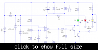
Based on PCB I drew a diagram of this circuit.
I hope that I don't do any mistake.


And this is not a good design
 
  • Like
Reactions: PG1995

    PG1995

    Points: 2
    Helpful Answer Positive Rating
Status
Not open for further replies.

Part and Inventory Search

Welcome to EDABoard.com

Sponsor

Back
Top