Vermes
Advanced Member level 4


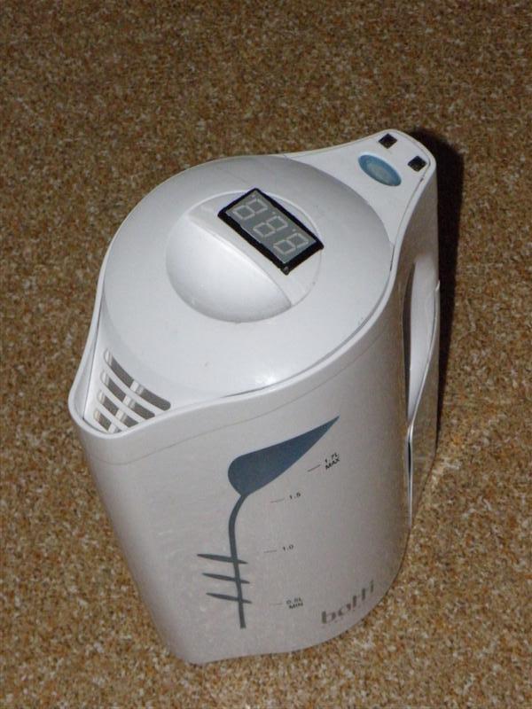
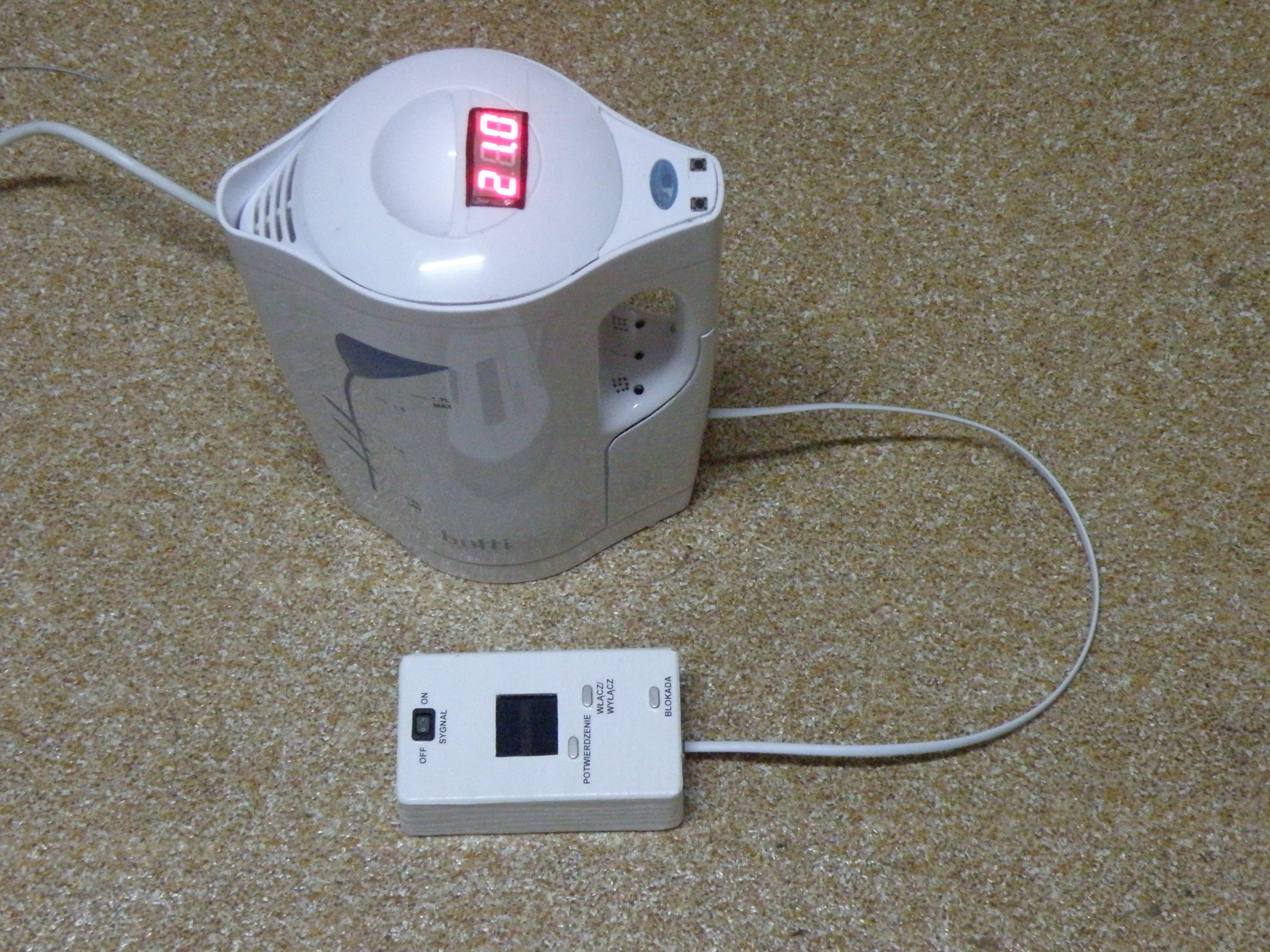
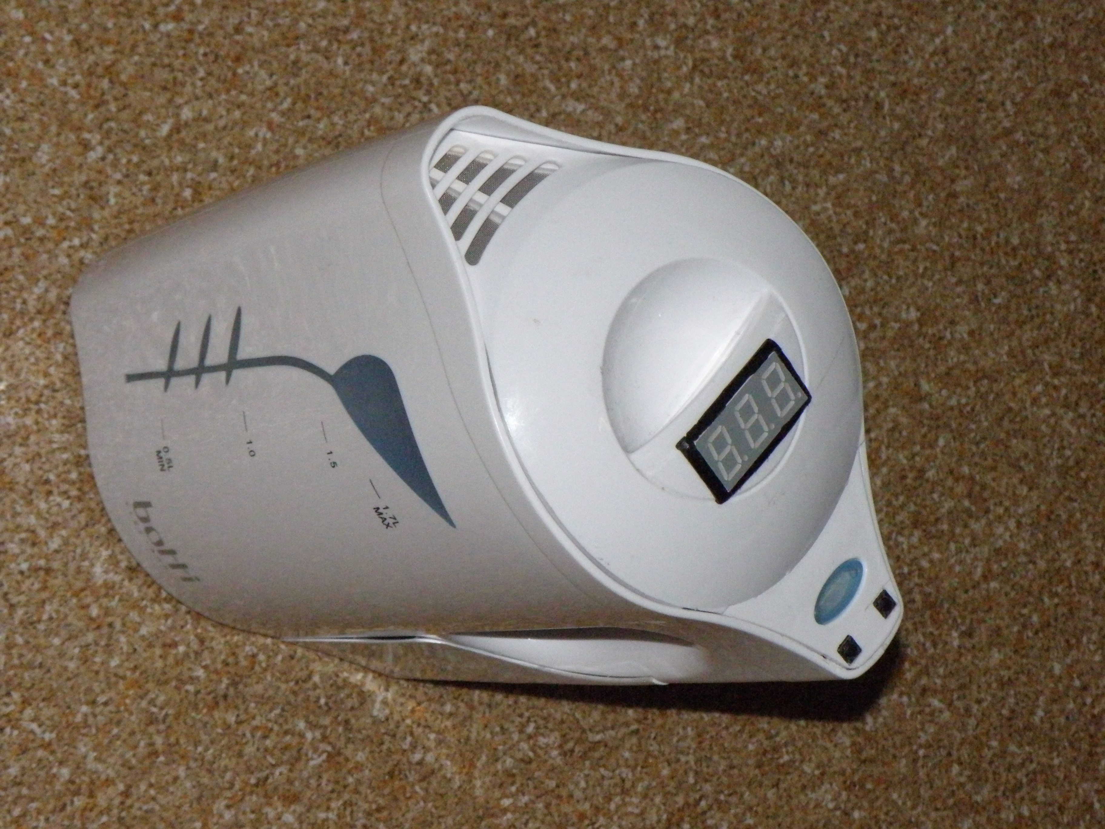
The main assumption was to build a kettle that displays water temperature with a possibility to set it at the desired value and to enable the device by a mobile phone.
When building, the simplest solutions were used. One of those is switching the kettle using the phone's backlight on, which is located in the GSM module.
The first problem was microcontroller little resistance to higher temperatures. To solve the problem, the board with the electronics was flooded with silicone adhesive from the bottom, what caused the slower absorption of heat, and the cover of the kettle was insulated by a thermal mat. After that, the temperature of the board with the electronics does not rise above 38 degrees Celsius.
Another problem was concerned the GSM module and was due to promotional text messages coming from the mobile network. This resulted in undesirable turning on the kettle. The solution turned out to be very simple and consisted of calling the mobile operator and claim no information about promotions and advertising.
Schema of the system in the kettle:
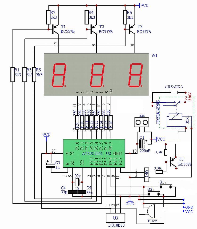
Description:
The main element of the system is AT89C2051 microcontroller, which was written in Bascom. It is clocked with a quartz resonator at a frequency of 12MHz, and two additional capacitors C4=C5=33pF, which allow the integrated generator 89C2051 work. The generator “drives” the entire microprocessor. Of course, the frequency of the resonator is highly dependent on the microcontroller speed. Through the electrolytic capacitor C3 (1uF) the processor is reset when you turn the powering voltage filtered by the capacitor C1 (220uF). This will provide a logical 1 on the R derivation, and therefore immediate interrupt of the operations and starting the cycle of the processor working from the beginning. The duration of the positive reset pulse depends on the frequency 12MHz and capacitor C1.
The supply voltage 5V is connected to the power connector. Resistors R9-R16 (330ohm) limit the current of the displays. Transistors T1-T3 (BC557B) along with resistors R1-R6 (3,3kohm) control the display anodes. Resistor 4,7kohm pulling up the 1-Wire bus (leg 9 of the U2) to the supply plus was soldered from the paths of the system. Sensor DS18B20 was used to proper and accurate measurement of water temperature and switching the kettle heater is operated by the 16A relay with 5V coil. In order to obtain the required 5V DC voltage, transformer 230V/7V was used.
Another system was GSM module. The system switches the kettle on the base of turning on the LED on the phone keypad. This task is implemented by NMOS transistor. After administration the voltage from the LED 2,85V that backlights the phone keypad to the source (ground) and the gate. The transistor will operate in two states, as a switch, starting the kettle by shorting the signal to ground.
Schema:
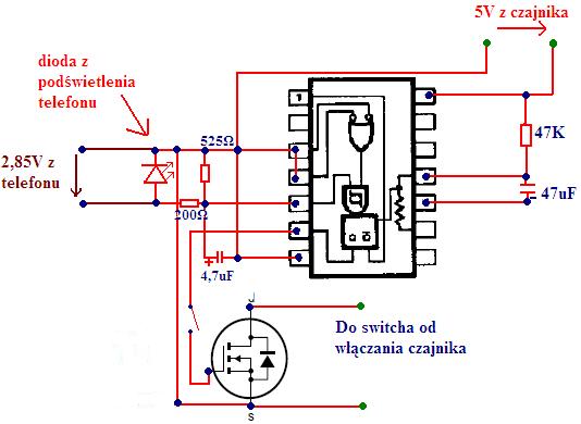
One of the problems in this part was long backlight of the keypad (about 15 seconds), and what is associated, long time of shorting the switch of switching the kettle. The solution was to use the monostable system UCY74121, which generates the desired pulse width. Positive triggering signal from the diode should be coupled to the fifth leg, and the third and fourth leg shorted to the mass. In this way, the system will generate a pulse with time T=0,69RC at the output (sixth leg). Resistor occurring in the formula has the value R=47kohm and is connected between +5V power supply and eleventh leg, while the capacitor C has the value of 47uF and is located between eleventh and tenth leg. In this way you can get the shorter pulse duration of fifteen seconds to one.
Another difficulty was so called “hanging one” at the input B while starting the system UCY74121. It is normal in TTL systems, but, because there is a diode at the input, that below the threshold voltage does not conduct electricity, low state (<0,8V) would not appear. This problem was eliminated by inserting three serially connected resistors between the input B and the mass, which gave a total value of 525ohm.
Other problem was slowly fading LEDs on the phone. Second impulse arising when turning on and off the backlight, caused switching on and off the kettle in a short time. It is caused by the phone processor sending many thousands of switching cycles with decreasing fill factor (PWM modulation) until the LED goes out. These impulses were suppressed by integrator system with time constant T=RC, where R=200ohm and C=4,7uF. After this correction, the system began to operate properly.
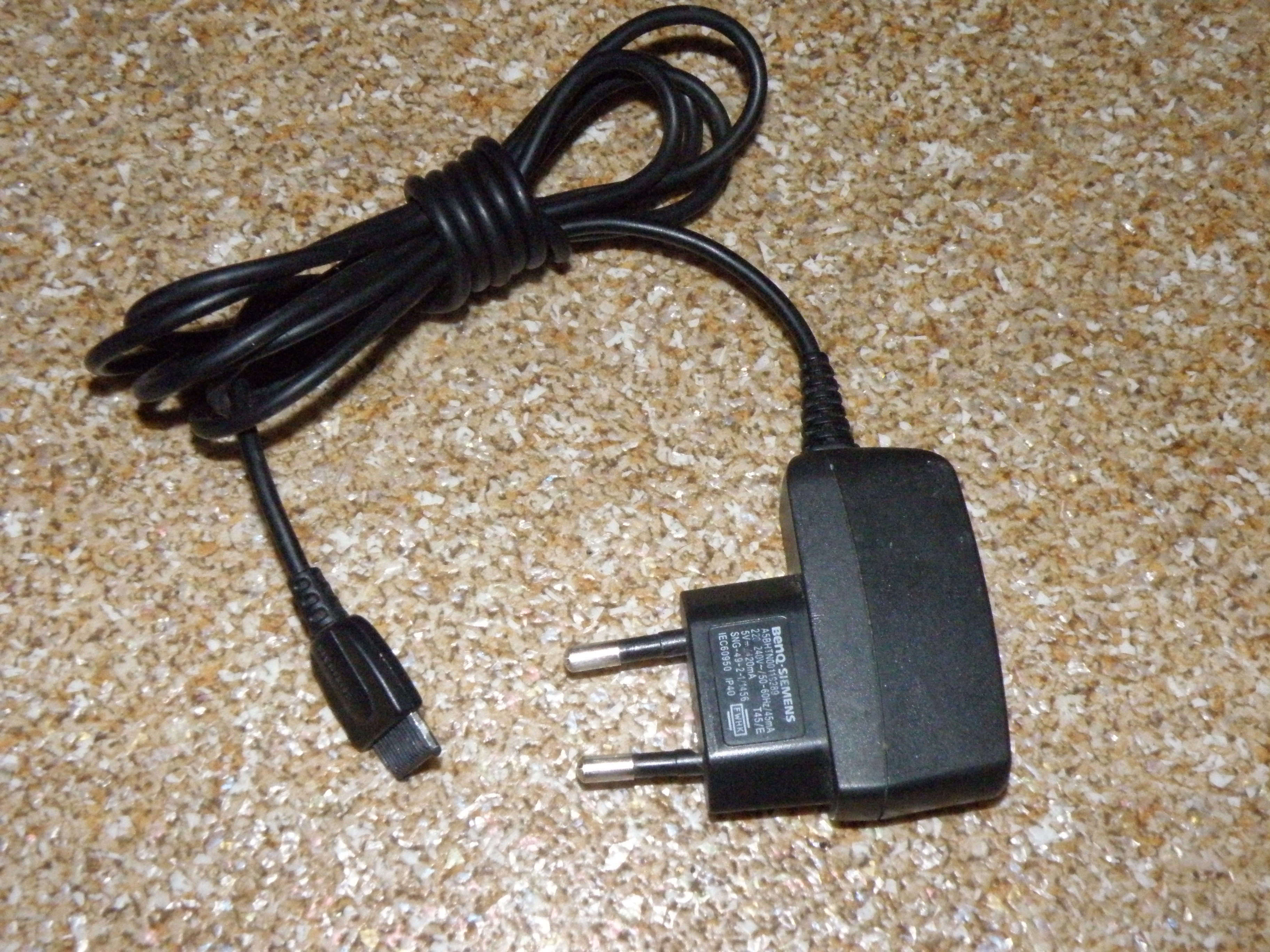
The GSM module is loaded DC from the ordinary mobile phone charger that is included in the kit. Module operating time when fully charged battery is approximately five days.
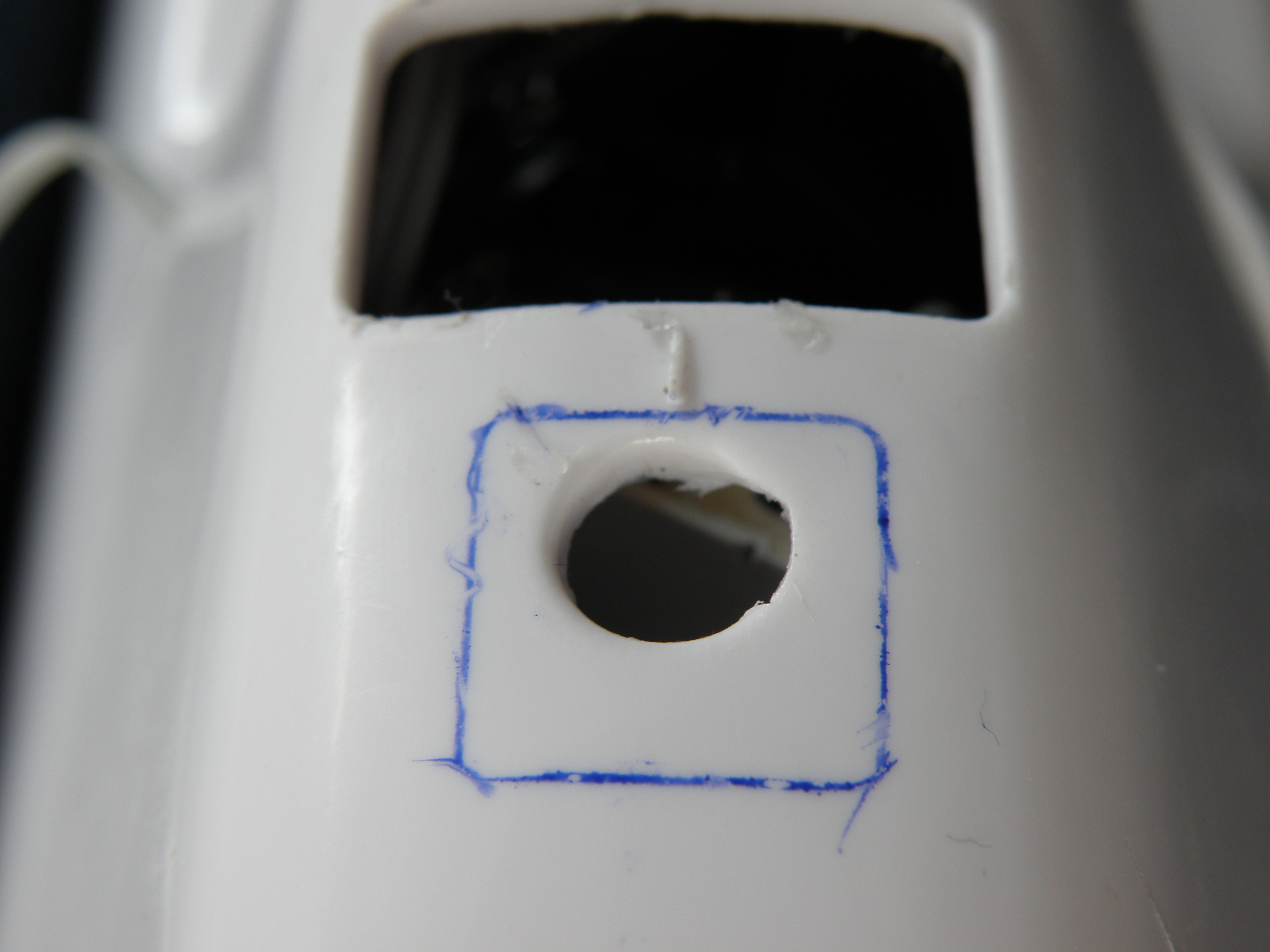
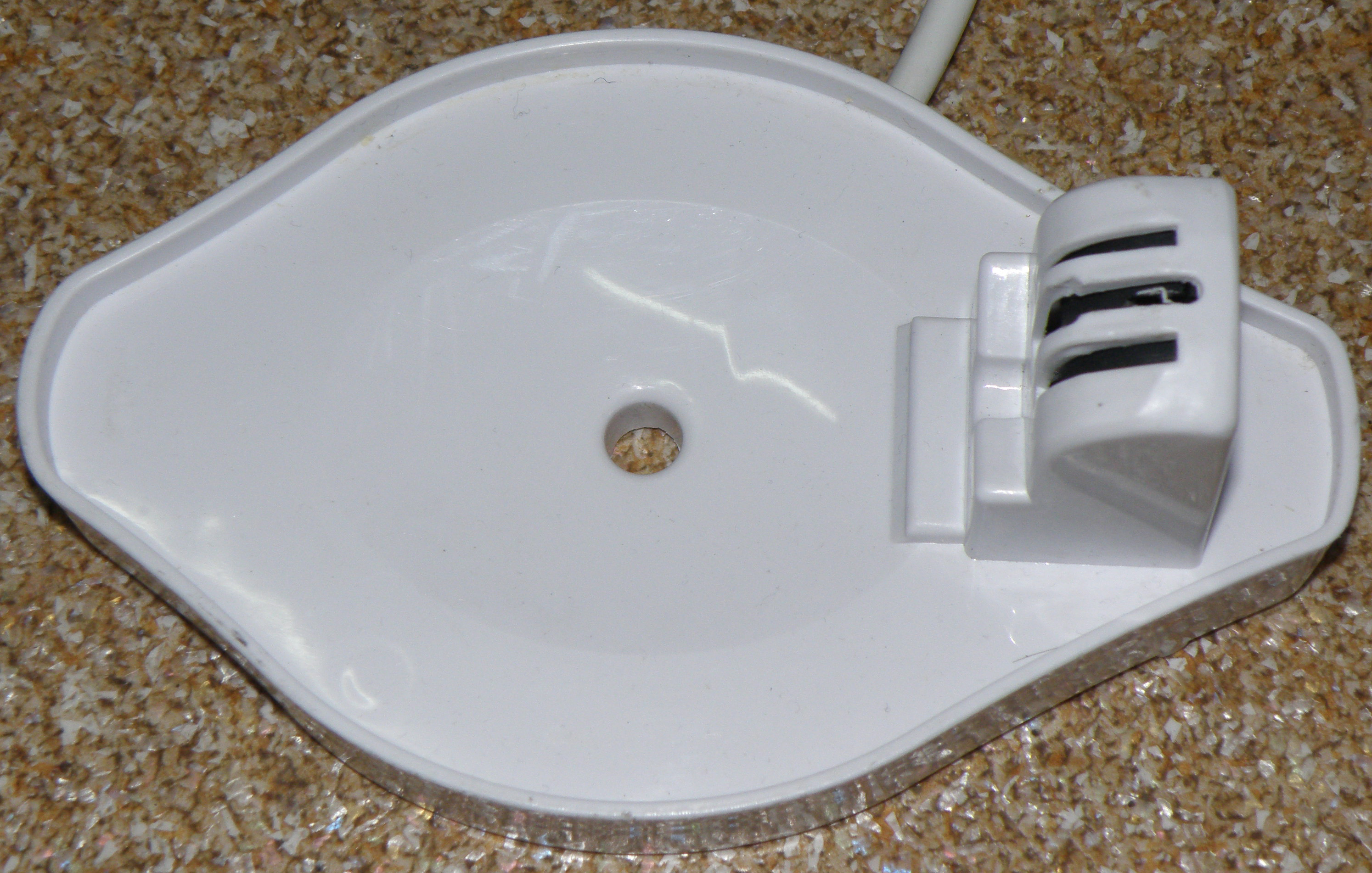
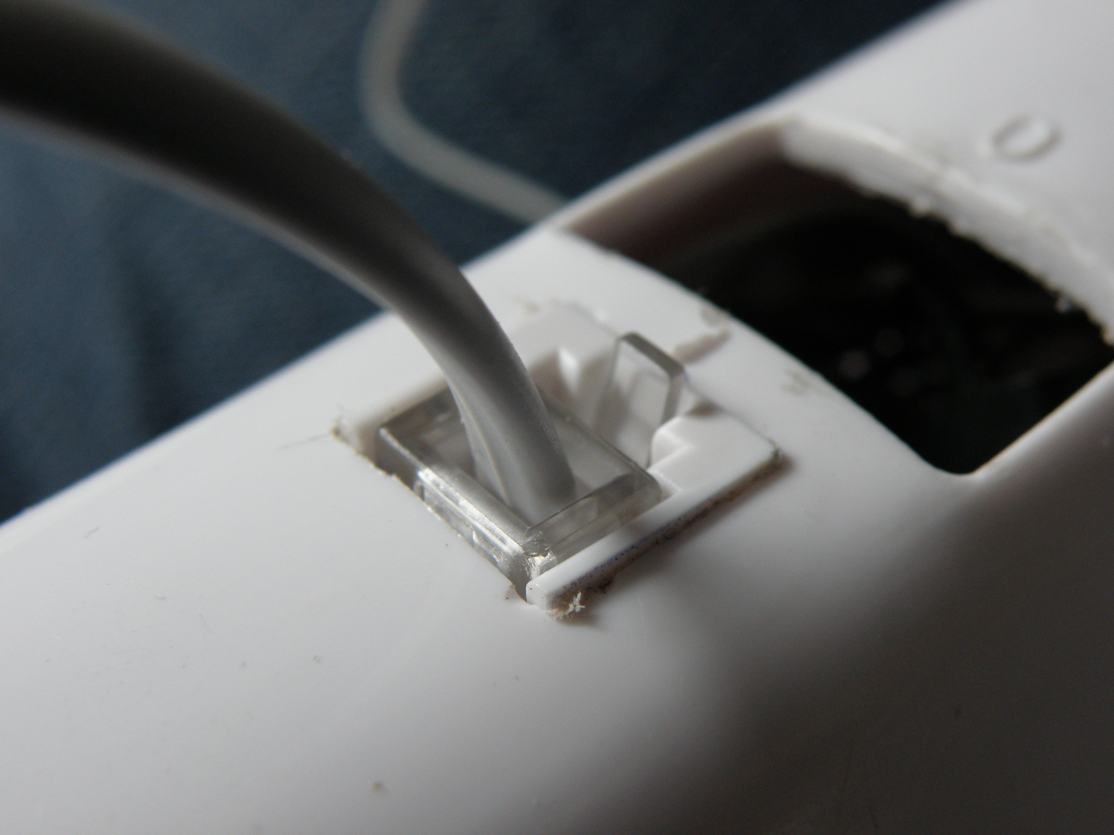
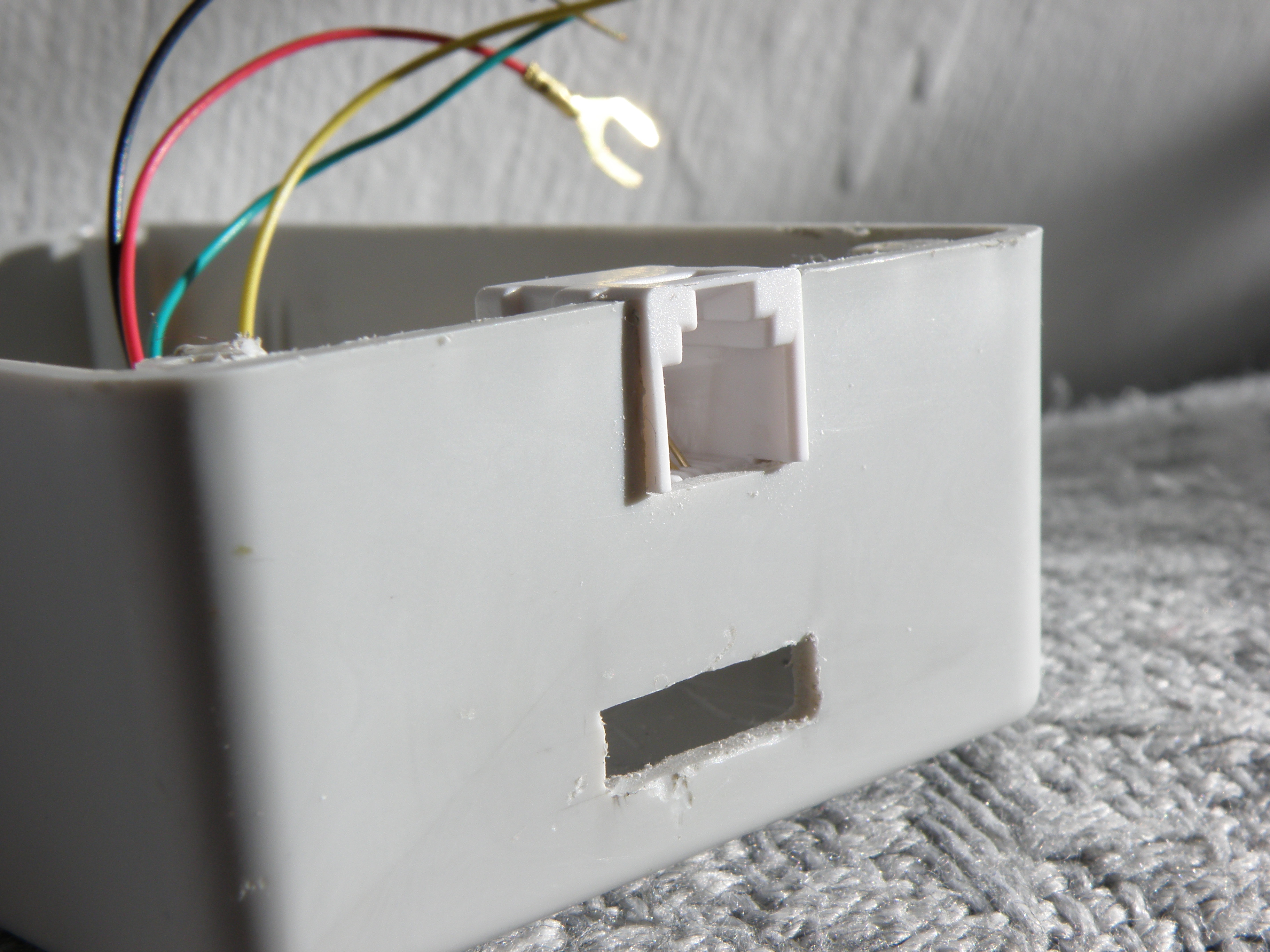
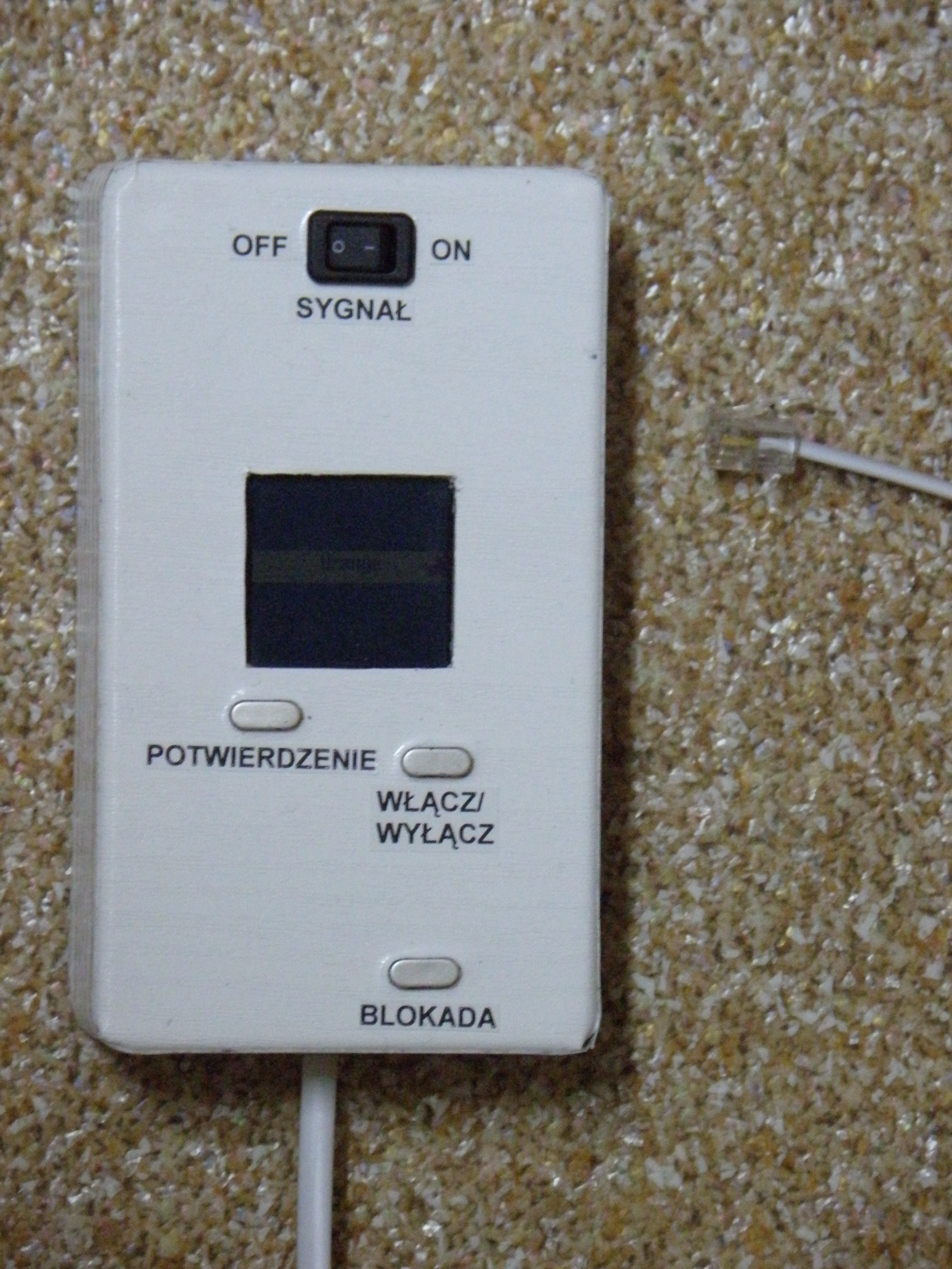
Below there are some photos and a short video:

Link to original thread (useful attachment) – Czajnik sterowany telefonem komórkowym