Continue to Site

Welcome to EDAboard.com

Welcome to our site! EDAboard.com is an international Electronics Discussion Forum focused on EDA software, circuits, schematics, books, theory, papers, asic, pld, 8051, DSP, Network, RF, Analog Design, PCB, Service Manuals... and a whole lot more! To participate you need to register. Registration is free. Click here to register now.

Op-amp basics. Working of AND and OR gate made using op-amp.

Status
Not open for further replies.

pd123

Junior Member level 1
Joined
Jun 23, 2011
Messages
19
Helped
0
Reputation
0
Reaction score
0
Trophy points
1,281
Location
India
Activity points
1,440
I found the following two images in the datasheet of LM399N. This give the basic circuit of the AND and OR gates using op-amp. I cannot understand their working. Perhaps I am missing some vital principle of Electrical basics. Please help me understand the working of the circuits.


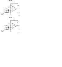
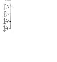
I am actually working on a circuit which has several inputs whose values are either 20mV or 400mV. Now I want to make a circuit which give an output when any of the inputs is 400mV. How can this be done?
 

Hi there... I think logism software can help you. it is open source software so you can download it from the web... thank you
 

I hope this gives you an idea.

LM139_Multi_in.jpg
 

Perhaps I should tell you more about what I am trying to do. I have a panel of photodiodes. The voltage of the resistor connected below the reverse biased photodiode increases when light falls on it. The voltage when no light falls on it is 20mV and when exposed to light it is 400mV. Now for the top five photo diodes of the panel, I am supposed to do the same work. So I thought about ORing the voltages to find out if any of the voltage outputs is 400mV and then giving only one output to the microcontroller.

I was wondering how wired-OR works and whether it can be used in my project. I will amplify the signals to give it to the micro controller.
 

lm399 is a comparator. this is similar to an OTA, which in turn is similar to an opamp. One major difference is that many comparators do not have a buffer on the output, further, they only have an open collector output. This means that they can either force the output to 0V or do nothing. This is where the external resistor comes into play -- when none of the comparators force the output to 0V, the external resistor will pull the output high.

It is important to realize that these circuits only work because of the open-collector output. other opamps that can both drive high and drive low cannot be used as they would be able to fight each other. the same applies to other logic IC's and microcontrollers that also have open-collector options.

the first picture shows how a comparator can be used for logic. in this case, the threshold is set up such that the output will only go high when either 1+ (or) or 3 (and) inputs are set to 5V. Because this is an analog comparator, the and gate could also be met by a single high-voltage input. likewise a "two or three" circuit (AB+BC+AC) could be constructed.
 
  • Like
Reactions: LvW

    LvW

    Points: 2
    Helpful Answer Positive Rating
It is important to realize that these circuits only work because of the open-collector output. other opamps that can both drive high and drive low cannot be used as they would be able to fight each other.

Very true !!!
 

In the first picture,the only difference shown between the AND and OR gate circuit is the resistor value at the inverting input. How does this work?

For my application which has outpus of 20mV and 400mV, should I amplify them first and then OR them?
 

In the first picture,the only difference shown between the AND and OR gate circuit is the resistor value at the inverting input. How does this work?
For the OR function, the reference voltage at the inverting input (75mV) is adjusted so that already one (i.e: any) of the 3 (logic) inputs is enough to get a logic "1" output. It's a replacement for a simple 3-input OR gate.

For the AND function, the reference voltage at the inverting input (375mV) is adjusted so that all 3 logic inputs must be logically "1" to achieve a logic "1" output. It's a replacement for a simple 3-input AND gate.

Both applications IMHO only make sense if you don't have or don't want to use a logic gate, or if you have a left-over opAmp and thus be able to avoid using another IC.

For my application which has outpus of 20mV and 400mV, should I amplify them first and then OR them?
I think you should use one comparator per input. If you need the OR function, you can use the schematic of your second picture.
 

Status
Not open for further replies.

Similar threads

Part and Inventory Search

Welcome to EDABoard.com

Sponsor

Back
Top