Felipebrz
Newbie level 4

Hi,
I'm just starting on the 18F family (using the 18F2550) and with the C18 compiler.
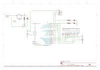
I created a circuit with two LEDs and the LCD. First I did a simple blinking leds example with it, which worked perfectly. I'm using the internal oscilator, configured to 8MHz.
The LCD only has written 1602F REV:I behind it, so I assume thats the LCD's controller. I've counted the dot matrix for each character and it looks like it is a 5x8 (even though it doesnt mention this kind in the xlcd library)
I am using MPLAB v8.73 and C18 v3.40. And using a PICkit2 to program my PIC.
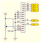
Seeing examples around the net, I have connected the LCD pins D4-D7 to RB0-RB3, while RS=RA0, RW=RA1 and E=RA2.
The main .c file is:
Below are the modified parts of the xlcd.h file:
on the project tree I have:
Source files:
- LCD.c
Header files:
- delays.h (in the same folder as LCD.c)
- p18f2550.h
- string.h (in the same folder as LCD.c)
- xlcd.h (in the same folder as LCD.c)
Linker script:
- 18f2550_g.lkr
And after all that, my LCD shows nothing!
I tried adjusting the brightness (using a 10k pot) but thats not the problem.
Can anyone help me with this? Any other information that may help, just say so.
Thanks!
I'm just starting on the 18F family (using the 18F2550) and with the C18 compiler.
I created a circuit with two LEDs and the LCD. First I did a simple blinking leds example with it, which worked perfectly. I'm using the internal oscilator, configured to 8MHz.
The LCD only has written 1602F REV:I behind it, so I assume thats the LCD's controller. I've counted the dot matrix for each character and it looks like it is a 5x8 (even though it doesnt mention this kind in the xlcd library)
I am using MPLAB v8.73 and C18 v3.40. And using a PICkit2 to program my PIC.
Seeing examples around the net, I have connected the LCD pins D4-D7 to RB0-RB3, while RS=RA0, RW=RA1 and E=RA2.
The main .c file is:
Code:
// Arquivos de cabeçalho
#include <p18f2550.h>			// Processador = 18F2550
#include <delays.h>				// Funções de delay do compilador C18:
#include <string.h>
#include "xlcd.h"				// Funções do display LCD 2x16
// 1 TCY = 4/FOSC ==> @ 8 MHz ==> 1 TCY = 0,5 us
//		Delay1TCY()		= 0,5 us
//		Delay10TCYx()	= 5 us
//		Delay100TCYx()	= 50 us
//		Delay1KTCYx()	= 500 us	= 0,5 ms
//		Delay10KTCYx()	= 5000 us	= 5 ms

// Configurações do processador
#pragma config PLLDIV = 1
#pragma config CPUDIV = OSC1_PLL2
#pragma config FOSC = INTOSCIO_EC		// Oscilador interno
#pragma config FCMEN = OFF
#pragma config IESO = OFF				// Troca de oscilador desabilitada
#pragma config PWRT = OFF				// Habilita o Power-up Timer (PWRT)
#pragma config BOR = OFF				// Brown-out Reset (BOR) habilitado somente no hardware
#pragma config VREGEN = ON				// Regulador de tensão da USB habilitado
#pragma config WDT = OFF				// Desabilita o Watchdog Timer (WDT)
#pragma config MCLRE = OFF				// MCLR desabilitado; RE3 = Input
#pragma config PBADEN = OFF				// RB0,1,2,3 e 4 configurado como I/O digital.
#pragma config LVP = OFF				// Desabilita o Low Voltage Program
#pragma config XINST = OFF				// Conjunto de instruções extendido desabilitado
#pragma config DEBUG = OFF				// Debugger desabilitado
#pragma config CP0 = OFF				// Proteção do bloco 0 desabilitada
#pragma config CP1 = OFF				// Proteção do bloco 1 desabilitada
#pragma config CP2 = OFF				// Proteção do bloco 2 desabilitada
#pragma config CP3 = OFF				// Proteção do bloco 3 desabilitada
#pragma config CPB = OFF				// Proteção do bloco de boot desabilitada
#pragma config CPD = OFF				// Proteção do bloco da EEPROM desabilitada
#pragma config WRT0 = OFF				// Proteção de escrita do bloco 0 desabilitada
#pragma config WRT1 = OFF				// Proteção de escrita do bloco 1 desabilitada
#pragma config WRT2 = OFF				// Proteção de escrita do bloco 2 desabilitada
#pragma config WRT3 = OFF				// Proteção de escrita do bloco 3 desabilitada
#pragma config WRTB = OFF				// Proteção de escrita do bloco de boot desabilitada
#pragma config WRTC = OFF				// Proteção de escrita do bloco de config desabilitada
#pragma config WRTD = OFF				// Proteção de escrita do bloco da EEPROM desabilitada

// Definições de variáveis de IO:
#define VERMr	PORTCbits.RC0			// LED vermelho grande (pino 11): leitura
#define VERMw	LATCbits.LATC0			// LED vermelho grande (pino 11): escrita
#define VERDr	PORTAbits.RA4			// LED verde grande (pino 6): leitura
#define VERDw	LATAbits.LATA4			// LED verde grande (pino 6): escrita

// Rotinas auxiliares
void DelayFor18TCY(void)
{
Nop();
Nop();
Nop();
Nop();
Nop();
Nop();
Nop();
Nop();
Nop();
Nop();
Nop();
Nop();
}

void DelayPORXLCD(void)
{
Delay1KTCYx(30);	// Delay of 15ms
					// Cycles = (TimeDelay * Fosc) / 4
					// Cycles = (15ms * 8MHz) / 4
					// Cycles = 30,000
return;
}

void DelayXLCD(void)
{
Delay1KTCYx(10);	// Delay of 5ms
					// Cycles = (TimeDelay * Fosc) / 4
					// Cycles = (5ms * 8MHz) / 4
					// Cycles = 10,000
return;
}

unsigned char lcd[17];

// Início do programa
void main(void)
{
Delay10KTCYx(190);
// Definição das variáveis locais

// Configurações de módulos
OSCCONbits.IRCF2=1;	// Configuração para clock de 8 MHz
OSCCONbits.IRCF1=1;
OSCCONbits.IRCF0=1;
OSCCONbits.SCS1=1;	// Oscilador interno para sistema
ADCON0=0b00000000;	// Módulo AD desligado (pag.265)
ADCON1=0b00001111; 	// Todas as portas são digitais (pag.266)
CMCON=0b00000111;	// Desliga os comparadores (pag. 277 e 278)

// Configuração de direção das portas
TRISA=0b00000000;
TRISB=0b00000000;
TRISC=0b00000000;

LATA=0b00000000; //Coloca o PORTA em 0V.
LATB=0b00000000; //Coloca o PORTA em 0V.
LATC=0b00000000; //Coloca o PORTA em 0V.

// Configurando LCD
OpenXLCD(FOUR_BIT & LINES_5X7);
while(BusyXLCD());
WriteCmdXLCD(DON & BLINK_OFF & CURSOR_OFF);
while(BusyXLCD());
WriteCmdXLCD(0x01);//clear display
memset(lcd,'\0',17);
strcpypgm2ram(lcd,"hello world");
putsXLCD(lcd);
while(1)
{
;
}
}
Below are the modified parts of the xlcd.h file:
Code:
#ifndef __XLCD_H
#define __XLCD_H
#include "p18f2550.h"
/* PIC18 XLCD peripheral routines.
 *
 *   Notes:
 *      - These libraries routines are written to support the
 *        Hitachi HD44780 LCD controller.
 *      - The user must define the following items:
 *          - The LCD interface type (4- or 8-bits)
 *          - If 4-bit mode
 *              - whether using the upper or lower nibble
 *          - The data port
 *              - The tris register for data port
 *              - The control signal ports and pins
 *              - The control signal port tris and pins
 *          - The user must provide three delay routines:
 *              - DelayFor18TCY() provides a 18 Tcy delay
 *              - DelayPORXLCD() provides at least 15ms delay
 *              - DelayXLCD() provides at least 5ms delay
 */

/* Interface type 8-bit or 4-bit
 * For 8-bit operation uncomment the #define BIT8
 */
/* #define BIT8 */

/* When in 4-bit interface define if the data is in the upper
 * or lower nibble.  For lower nibble, comment the #define UPPER
 */
/* #define UPPER */

/* DATA_PORT defines the port to which the LCD data lines are connected */
 #define DATA_PORT      		PORTB
 #define TRIS_DATA_PORT 		TRISB

/* CTRL_PORT defines the port where the control lines are connected.
 * These are just samples, change to match your application.
 */
 #define RW_PIN   LATAbits.LATA1   		/* PORT for RW */
 #define TRIS_RW  TRISAbits.TRISA1    	/* TRIS for RW */

 #define RS_PIN   LATAbits.LATA0   		/* PORT for RS */
 #define TRIS_RS  TRISAbits.TRISA0    	/* TRIS for RS */

 #define E_PIN    LATAbits.LATA2  		/* PORT for D  */
 #define TRIS_E   TRISAbits.TRISA2    	/* TRIS for E  */
on the project tree I have:
Source files:
- LCD.c
Header files:
- delays.h (in the same folder as LCD.c)
- p18f2550.h
- string.h (in the same folder as LCD.c)
- xlcd.h (in the same folder as LCD.c)
Linker script:
- 18f2550_g.lkr
And after all that, my LCD shows nothing!
I tried adjusting the brightness (using a 10k pot) but thats not the problem.
Can anyone help me with this? Any other information that may help, just say so.
Thanks!


