Vermes
Advanced Member level 4


Construction
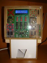
The machine consists of two parts.
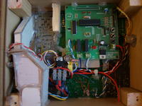
First is equipped with a driver and front panel, the second one is with coin container, trapdoor mechanism and power supply. Unfortunately, there is no pictures of the mechanism, because it's secured with a carton and hot glued. Universal SMPS is set on 7,5V, because it's enough and the stabilizers don't heat up too much.
Front panel consists of different sets for self-assembly with LED diodes, put together. They aim is to make the look of device more attractive. In the side of the housing, there is a little lock with a built-in switch from a telephone. Twisting the key in the lock is followed by withdrawal of money from the inside. Of course, money would also be paid if somebody wins. The driver is a test plate with relays installed.
How it works
Firstly, the driver activates the engine to raise the ramp in the event as if it was lowered. As it is lowered, the coins are shedding. Then, there is the main inscription 'Throw a coin, grab a fortune'.
After throwing a coin to the hole in the upper side of the machine, as it drops, it hits a protruding element connected with the contact element. It sends a low state to Atmega8 port.
Then you have two chances. By pulling a lever, the relay attaches, shorting paths on the J-96 plate, which normally would be shortened by the button. This causes the rotation of the 'drums', which are the LEDs. PNP transistors are connected in series to the cathodes of green LEDs, which makes, that current would flow through the transistors to the processor port. It happens only when all three green LEDs would be lit. In this case, the ramp is lowered and the money would shed from the hole at the bottom of the machine.

The machine isn't used for hazard purposes – it's only a toy model.
Link to original thread (useful attachment) – Automat "Jednoręki bandyta"
