Vermes
Advanced Member level 4

- Joined
- Aug 2, 2011
- Messages
- 1,163
- Helped
- 0
- Reputation
- 0
- Reaction score
- 0
- Trophy points
- 1,316
- Activity points
- 22,318
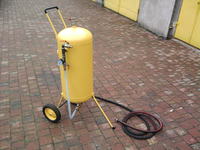
The sand spreader
Elements needed to build a sand spreader:
- LPG tank 55l
- installations like ball valves, elbows, gauge, nozzles, etc.
- the cylinder cover from the valve
- rods forming chassis and handle
- wheels
- hoses, bands
- carbide nozzles 3mm
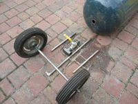
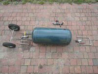
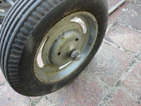
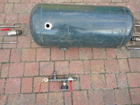
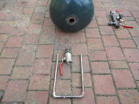
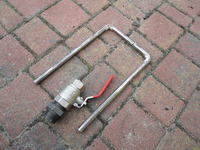
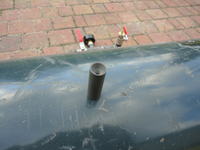
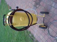
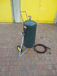
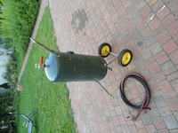
Welding was necessary because of the cast iron nozzles. Also, black threaded pipes were useful to seal the tank after welding. The holes for welding the nozzles were made with a simple drill. The valve at the top of the tank (the sand infeed) is 1”, the powering installation in the side of the tank is 1/2”, and the valve for dosing the sand is 3/4” - it's a gas valve. Mounting of the carbide nozzles was made without complicated bindings. A hole in the hose was enlarged with a small cutter and the nozzle was secured with bends. A place after the LPG tank valve was sealed with a precisely brought steel lid made by a turner. Then the holes were drilled and everything was finished with silicone. It could be welded as well. The whole device was lacquered.
The compressor
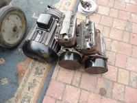
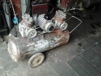
To made the compressor, two Jelcz compressors were needed. Their performance reaches 460l/min, so, taken together, they should reach about 900l/min. In both compressors, the seals were changed into new ones, valves and the finishing were cleaned.
Then a tank for 140l with 5mm wall thickness was needed. It was bought with a whole compressor and three-phase engine (4kW 1400rpm). Other important components like safety valve, electrical switch, pipes, start/stop button were also needed.
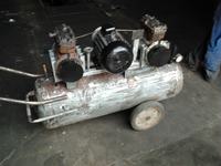
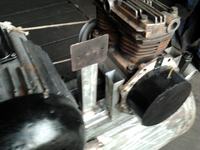
Below there's a picture of a smaller compressor – also self made.
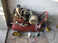
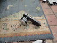
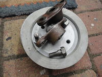
The HS31 compressors need lubrication. To make this, a support pump from a Polonez and the pulleys were needed. Then a drive wheel for the oil steering pump to the motor pulley had to be done. A tee was self made from soldered cooper pipes. The compressor covers were made with the same method, from a copper plate. The HS31 compressor has an output shaft on both sides, but the sealing is only on one side. That is why the side with the sealing was used for the pulley and the second one was sealed and equipped with the oil flow.
Things needed:
- profiles of the frame, plate
- pipes 1/2”, elbows
- check valves
- power steering pump from a Polonez
- mower fuel tank
- V-belts
- tubing, bands
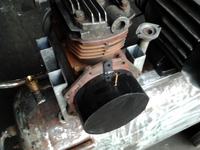
- 2x air filter from a Fiat 126p
- turning the pulley mounting for compressors
- pulleys
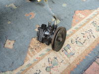
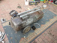
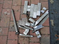
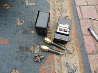
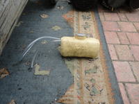
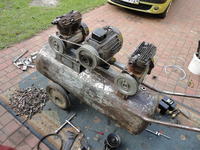
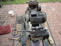
Oil flows into the old mover fuel tank by hoses and back to the oil pump. Each compressor has its own check valve. The belt tension is adjustable by rising the engine, the power steering pump has an additional adjustment.
Link to original thread – Zestaw do piaskowania DIY Kompresor + Piaskarka