Sajjadkhan
Full Member level 5

- Joined
- Sep 25, 2010
- Messages
- 307
- Helped
- 17
- Reputation
- 34
- Reaction score
- 16
- Trophy points
- 1,298
- Location
- Rawalpindi,Pakistan
- Activity points
- 4,199
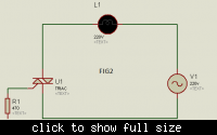
I am driving a heater wire from Triac BT136 which previously was controlled by a relay.
Heater wire resistance : 78 Ohms
Heater wire Inductance: 0.47mH (measured by digital multimeter---UT70A)
Heater Capacitance: 0.15uF (measured by digital multimeter---UT70A)
Heater wire current: 2.55 Amps (RMS) at 220V(RMS)
I just have to switch it off and ON, no big deal. I now that it is sensitive to dV/dt and di/dt.
The triac can switch on by itself if these rates of change increases then the given in datasheet.
My question is why snubber circuit it used? When i say why then i must also ask that is snubber circuit for the protection from AC 220V or is it protection from the inductive load? If not a complete sine wave i.e. if it is started from some angle then sudden starting of wave has instantaneous change but why using snubber when inductor itself limits di/dt. If this is true then the only thing left is dv/dt. Discharging is not an issue here as it discharges with the sine wave(not instantaneous).
Now if my above observation is correct then look at this figure:
https://3.bp.blogspot.com/-IiQvg1Ew.../azFA0eH-viw/s1600/MOC3021+Inductive+Load.bmp
Consider the snubber circuit with the triac (R = 39 Ohm and cap =0.01uF).Now if dv/dt change is to be controlled then the output should have been chosen at the 0.01uF capacitor node i.e. node between capacitor and resistor is connected. but the capacitor and resistor are in series which are parallel to the triac so any change at RC series snubber will be at triac. So it sill wont protect dv/dt, correct me if i am wrong.yes load is in series too but it will still limit di/dt not dv/dt i think.
2. If i am wrong then will this snubber circuit will protect my heater to stay off at square wave inverter?


