Welcome to our site! EDAboard.com is an international Electronics Discussion Forum focused on EDA software, circuits, schematics, books, theory, papers, asic, pld, 8051, DSP, Network, RF, Analog Design, PCB, Service Manuals... and a whole lot more! To participate you need to register. Registration is free. Click here to register now.
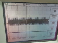
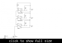
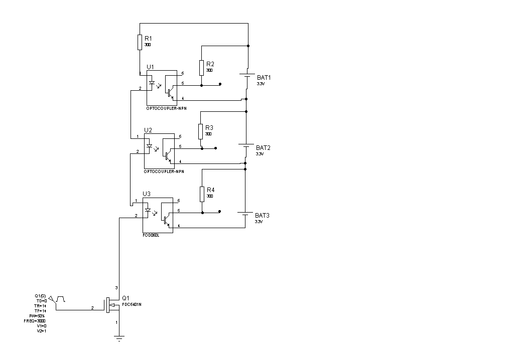
Hi, please i am blocked in this project and i need help, attached is the circuit of the project, the problem is with the optocoupler output, please i need help*
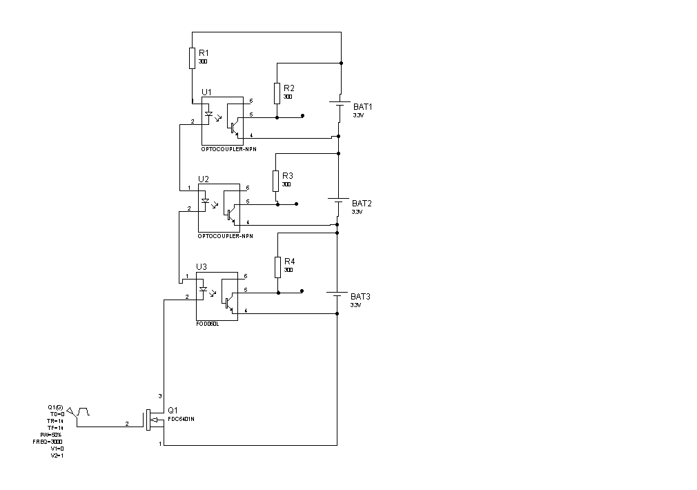
My first thoughts are what are you taking the output from. Each of the opto-outputs is sittling 3.3v above the previous one, relative to the negative side of the bottom battery. There is no zero volt reference point for the output side and so no current can flow through the FET or LED side.
It would also be a good idea to add a resistor between the gate and source of the FET to ensure it turns off in the absence of drive voltage.
That is a different schematic than the one you showed first!
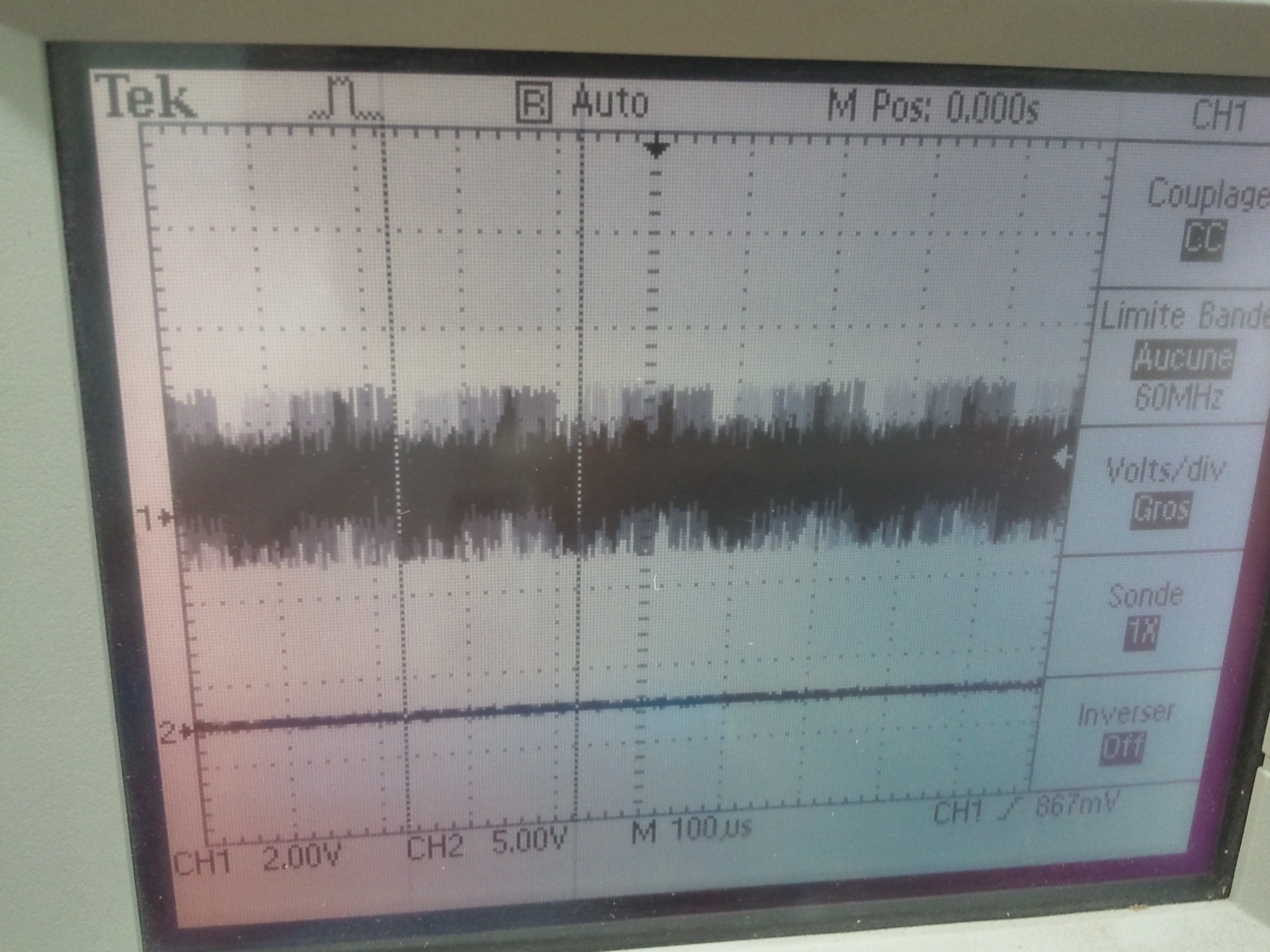
Are you connecting the oscilloscope ground to the source of the FET ?
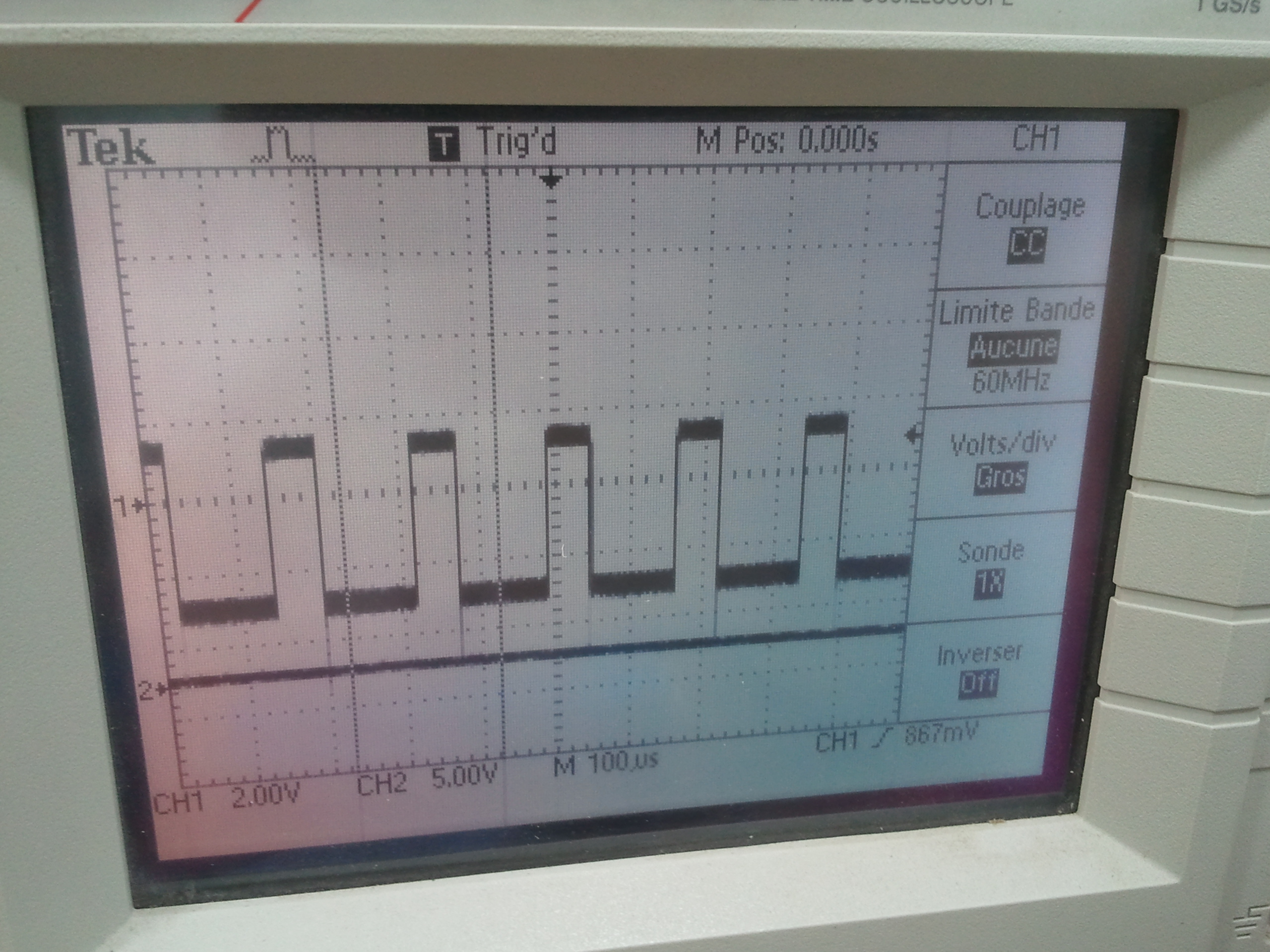
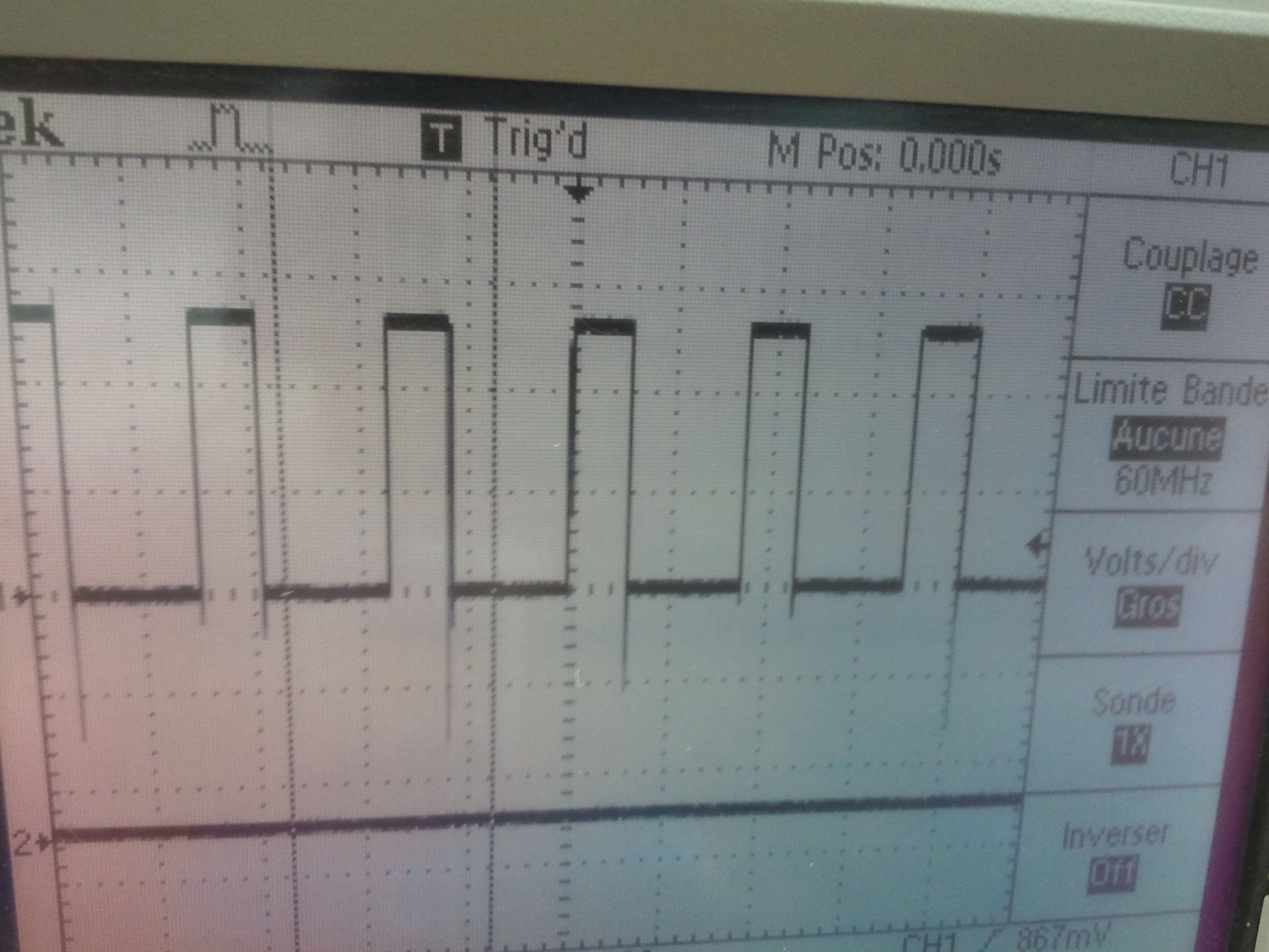
What are you actually trying to achieve? All you should get outputs at 0, 3.3V and 6.6V when the FET is turned ON and at 3.3V, 6.6V and 9.9V when it is turned off. These figures assume you are not significantly loading the outputs.
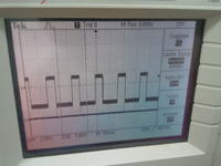
You should clarify about the voltage probe connections first. It's not understandable, how you get a negative output voltage in the second waveform. One could guess, that the first waveform is mainly showing unsuitable trigger conditions.
I think you need to rethink your circuit. As mentioned by others here, there's no good reference for the opto outputs, as each one is sitting on some battery. And are those really batteries in your circuit? Where do you have you scope probe ground lead connected? Ground? And what's really the point of this circuit? It might help if you could explain that.
This site uses cookies to help personalise content, tailor your experience and to keep you logged in if you register.
By continuing to use this site, you are consenting to our use of cookies.