dksoba
Member level 2

Hi everyone,
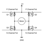
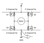
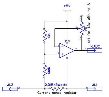
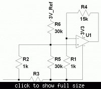
I want to create a low side current sensing circuit. The goal is to sense a 0-5 amp magnitude current by using a kelvin resistor, differential op amp, and a 0-3v ADC (from a microcontroller). The problem I have is that the direction of the current is not guaranteed. This is a motor controller, so sometimes the motor will drive current from the ground to the voltage source via the MOSFET's diodes. I want to be able to measure this current as well as the forward current. If I use a differential amplifier to amplify the voltage from the kelvin resistor (4-wire resistor), then I will get some negative voltage when the current is negative. To solve this, I think I need a second amplifier to add a voltage offset to the first amplifier. AKA, the op amp stages would be like this:
stage 1: Amplify the small signal from current sensing resistor (4-wire resistor seems to be the way to go, but correct me if I'm wrong, I'm still relatively new to all of this). The output from here would be -3v to 3v. I guess this means I'd need a -3.3v power supply, or some negative power supply, for this op amp.
stage 2: Add 3v to the output of stage 1, so that we have a 0-6v output. Then I can use a resistor divider to get 0-3v output.
Maybe I'm making this too complicated, so please help me!
Thanks,
Matt

