Continue to Site

Welcome to EDAboard.com

Welcome to our site! EDAboard.com is an international Electronics Discussion Forum focused on EDA software, circuits, schematics, books, theory, papers, asic, pld, 8051, DSP, Network, RF, Analog Design, PCB, Service Manuals... and a whole lot more! To participate you need to register. Registration is free. Click here to register now.

12v DC Motor no control

Status
Not open for further replies.

City fan

Member level 1
Member level 1
Joined
Aug 22, 2011
Messages
35
Helped
0
Reputation
0
Reaction score
0
Trophy points
1,286
Location
UK
Visit site
Activity points
1,544
Could someone please give me an idea of what could be the problem with my electric golf trolley,
the motor when switched on goes on fast speed, with no control from the pot.
There are no battery condition lights either.
There is one P60NF06 Mosfet, a Shottsky rectifier, 3 transistors S8050x2/S8550, and 1 78L05 regulater.
I do realise this is all a bit vague. If it means removing and testing items where should I start?
 

There are no battery condition lights either
Ist see if ground connection to the control board is properly connected.
There is one P60NF06 Mosfet, a Shottsky rectifier, 3 transistors S8050x2/S8550, and 1 78L05 regulater.
First check FET this way.
Disconnect motor terminal from FET output and connect a bulb of same voltage instead to test board easily. See for obvios burnt FET. FET gate has a series resistor connecting to drive circuit. Desolder one side and pull out. Now make a bridge between source and gate.Now check for swithed position, if it is same
FET is damaged. If it is now turned off FET is ok.
 
Last edited:
Ist see if ground connection to the control board is properly connected.

First check FETs this way.
Disconnect motor terminal from FETs output and connect a bulb of same voltage instead to test board easily. See for obvios burnt FETs FETs gate has a series resistor connecting to drive circuit. Desolder one side and pull out Now make a bridge between source and gate.Now check for swithed position, if it is same
some or all of FETs are damaged. If it is now turned off FET is ok.

Thank you for your help will try as you suggest,
The earth is good soldered joint.
 

Tried as you said, Mosfet tested ok.

Removed and tested transistors, the S8550 tests ok, but both S 8050 are conducting from E to C as well as BE-BC.

I've located S9013 as replcements only difference is HFE has a minimum of 64 instead of 85, would these be ok to use.
 

Yes it will work but you also look for the cause also. For example supply voltage regulation,cotaminated pcb etc.
 
Thank you Alertlinks, there is a voltage regulator a 78L05 will remove and test.
If faulty I will replace that and both the transistors.
I'm sure we are on the right track, thanks.
 

Hi, have changed both S8050 transistors with S9013's, also changed voltage regulator although that tested ok.
I removed and tested the mosfet that was ok, as was the S8550, only thing was, had to connect 9v battery to mosfet gate + with locating tab - and vice versa to get it to switch on and off, I assummed that was normal as a new mosfet worked the same way.
I also changed 16 ic at the same time.
Maybe it's time to thank you for your help and bin it.
I do suppose there could be a manufacturing fault as the unit was new.
 

Which is the pwm ic used(16)? Maybe sg3524 or tl494. Is it working ok now.It happened to me also transistor and ic burnt without a reason withen few hours, replaced with new ones then workd ok.maybe not of good quality.
 
Last edited:
Thanks, the ic is a SN74HC139N, there is also an 8dil IC CY8C22113 havn't tried that as not easy to find, after that there's only resisters and condensers, and one relay which tested ok, as did the condensers.
I'm begining to think that the problem is in the manufacture/layout.
Not sure how to test the IC's.
 

CY8C22113 is microcontroller chip which is programmed with company software and probably is locked.

**broken link removed**
Technical/Catalog Information CY8C22113-24PI
Vendor Cypress Semiconductor Corp
Category Integrated Circuits (ICs)
Program Memory Size 2KB (2K x 8)
RAM Size 256 x 8
Number of I /O 6
Package / Case 8-DIP (0.300", 7.62mm)
Speed 24MHz
Oscillator Type Internal
Packaging Tube
Program Memory Type FLASH
EEPROM Size -
Core Processor M8C
Data Converters A/D 2x14b; D/A 1x9b
Core Size 8-Bit
Operating Temperature -40°C ~ 85°C
Connectivity I²C, SPI, UART/USART
Peripherals LVD, POR, PWM, WDT
Voltage - Supply (Vcc/Vdd) 3 V ~ 5.25 V
Lead Free Status Contains Lead
RoHS Status RoHS Non-Compliant
Other Names CY8C22113 24PI
CY8C2211324PI
428 1544 5 ND
42815445ND
428-1544-5


SN74HC139N is a digital ic which can be found and much more chances of defect than microcotroller.

http://www.ti.com/lit/ds/symlink/sn74hc139.pdf

Check power supply to ics. Check if any of ic get warm after few minutes of power applied. Check digital function of ic by
reading voltage levels on input and ouput pins according to truth table in datasheet.
There are no battery condition lights either
Trace why lights are not lit, see in circuit which components are drivig them.

---------- Post added at 02:27 ---------- Previous post was at 01:32 ----------

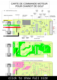
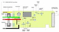
I found your board detail.
 
Thanks thats brilliant! try and do as you say, maybe a couple of days will let you know how it goes.

As you've most likely worked out i'm not to experienced on the diagnois side.
 

8946933.jpg
Output and drive circuit can be tested ok by shortening b and c of 8050 transistor right above the two ics near switch connector. Pin 9 of ic SN74HC139N is driving this transistor.It should be high to stop the motor.and lo to start motor.If voltage onthis pin is observed with meter, 5V means motor speed 0 .Speed will be inversly proportioal to voltage on the pin ie less votage means mor speed.Cause of fault seems to me is initially connecting battery with reverse polarity because there is no reverse battery protection. SN74HC139N is also driving indictors directly. This ic is most dougt full if 5V supply to it is ok between pin 8 and16.
 
Last edited:
Studied the board diagram only difference i can see is an extra condenser in between the verical resistor and third from top pin on connecter plug (right end). On this board pin 6 on chip goes to third outlet (lights) connecter through a resistor.
Checked battery supply cable to board, Torberry Anderson plug wired with red end on black lead, and vice versa. This must be problem!!!
I will follow your test procedure tomorrow and change chip if necessary, will also change battery polarity.
 

No you should not change battery polarity without checking first. You can check it with multimeter or see the marking on battery terminals. Red to +ve and black to -ve.If cart is moving forward then probably its ok because i dont see any swich for reverse operation.I meant to say if battery terminals are conected wrong way for a while, it could destroy the board. If it is still in wrong way then maybe you have to change transistors again.Check Switch and relay are on positive side and a thick jumper wire on board near FET negative as Torberry Anderson plug has no male/female.
 
Last edited:
Have checked termination from battery to board, with the torberry lead reversed it is correct and the red wire then goes from + on battery to plate on board attached to relay T connection.
I've changed chip SN74HC139N results are the same, motor runs fast at all times.
The results when doing tests you suggested are, short B and C on S8050 with the switch off 9 reads 12.6 volts. switched on terminal 9 reads 11.6 volts and motor stops.
The voltage reading between 8 and 16 = 0v. switch on =0.69v.
I've now at different times changed most items exept for the small condensers, resistors and chip cyb8c22113.
 

One thing i noted if battery connected wrong way, relay will not operate and motor will not run but board will get damaged.
Probably it happend in first place. Then corrected but damage is done.

short B and C on S8050 switched on terminal 9 reads 11.6 volts and motor stops.
This test shows FET and driver stage is working ok Motor stops when there is apropriate signal. Soits good you have fixed this stage.
Voltage readings are not right. Probably you have not measured it right. -ve(black) lead of multimeter shoud be attached to -ve on board and voltages tested with positive lead. Switch disconnects +12V to drive stage and regulator ic.

In post #7 you said
I also changed 16 ic at the same time.
.
I assumed it dip16. Now
I've changed chip SN74HC139N
Is it same

You have to take readings with power switch on. ICs are fed with +5V.So pin #9 cant be more than 5V. .69V could be between B and C of S8050.
Earlier you tested 78l05 regulator ic and even changed it supplies +5 volts to ics and display LEDs(lights). As you can see from bottom side of pcb center pin of 78l05 is connected to ground (negative) and pin 8 of SN74HC139N and pin 4 of cyb8c22113 also connected to ground .Similarly pin 16 of SN74HC139N and pin 8 of cyb8c22113 are connected with 78l05 output which should be +5V in on position.So how it comes,
switch on =0.69v
Now there are few posibilties,
1.If there is +5V present on regutor output (the other end is connected with with +12V) and not on pin 16 of SN74HC139N, then the track is broken.
2. 78l05 is damaged.
3.There is short cicuit, it may be ic shorted from inside any ic
Now first confirm regulator is supplying +5V desoldering and pulling out output lead and checking with multimeter by connecting with +lead. Negative lead goes to ground.

Then check for short between pin $4 and 8 of processor taking resistance with power off.
 
Last edited:
  • Like
Reactions: City fan

    V

    Points: 2
    Helpful Answer Positive Rating

    City fan

    Points: 2
    Helpful Answer Positive Rating
Just to clarify 16ic is the same unit as SN74HC139N.
Did more tests today hope i've got it right this time,
With B and C shorted together on transistor and switched on, voltage at 9 on chip = 0.75V motor running fast.
Tested at 16 and 8 reading 0.93, reading at regulator 5.16, checked through circuit, track broken on board. Repaired break, retested reading is now 4.97 from both 8 on processor and 16 on 16ic.
Resistance between 4 and 8 on processor (CYB8C22113) =3.550ohms.
Retested all tracks from transistors all seem ok.
Tried with new pot. Unfortunately I still have same result.
Do you think there is possibly a fault with the differences in design at right end of board where there is an extra condenser 10uF/16v on your plan, the best I can work out the terminal 6 from the chip on my board goes to 3rd pin on multi plug via a resistor.
I could try and design my board as your plan if I could work out where terminal at top right goes from 3rd pin.
 

The extra condensor is just put there for filtering noise coming from pot wires. It is not critical, circuit will work without it
Resistance between 4 and 8 on processor (CYB8C22113) =3.550ohms.
.
If resistance be that low, it would have shorted 5V supply. It may have been in Kohm range. As you have restored 5V to ic, so lets just forget it for time being.
There.is 1001 options for last resort. but first give our board a try.

Speed controller circuit can be divided in 4 stages.
1. power supply
2. Output
3. Driver for output
4. Control
Power supply is ok ie 12V and 5V is ok.
Output stage consists power fet, diode is ok as tested.
Driver stage need more observation as

earlier
short B and C on S8050 switched on terminal 9 reads 11.6 volts and motor stops.
now

With B and C shorted together on transistor and switched on, voltage at 9 on chip = 0.75V motor running fast.

Lets see relevent components of driver and output stage
on board.


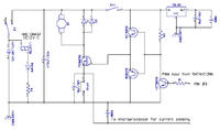
I drew a schematics for this portion.

Trouble shooting should be done in logical manner. From most suspected to least as numbered. For example if you suspect a bug in software of microcontroller and in the end a blown fuse is found.

29_1315312064.jpg

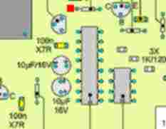
Pull out one side of resistance marked with red dot. Now connect this end with 5v with a small wire, motor should stop runnig. If it does not short E and C of transistor on the other side of the resistor. Now if it does then change this transistor.
After that we 'll see about the controller.
Meanwhile also check the 5v supply to lower end of connector attached to one wire of pot and display LEDs.
 
Last edited:
I do thank you for all your help, will try your suggestions tomorrow,
 

Status
Not open for further replies.

Part and Inventory Search

Welcome to EDABoard.com

Sponsor

Back
Top