Continue to Site

Welcome to EDAboard.com

Welcome to our site! EDAboard.com is an international Electronics Discussion Forum focused on EDA software, circuits, schematics, books, theory, papers, asic, pld, 8051, DSP, Network, RF, Analog Design, PCB, Service Manuals... and a whole lot more! To participate you need to register. Registration is free. Click here to register now.

horizontal white lines problem in Hitachi CRT TV..

Status
Not open for further replies.

ajex

Member level 4
Member level 4
Joined
Nov 7, 2009
Messages
70
Helped
6
Reputation
12
Reaction score
6
Trophy points
1,288
Location
Sri lanka
Activity points
1,813
Have good picture and sound on my color crt tv, but there are horizontal white lines in front of pictures. when I control the screen on flyback changing the intensity of this lines. how to remove this lines...? pleaaaaase help me.. :roll:

thank you..
 

First, need to know the exact model of the CRT TV.
Second, a picture of the screen will help understanding the real problems.

Usually lines which covers parts of the screen are two types:
1)- Lines usually cover part of the screen but not whole screen.
mostly caused by a fault on the vertical circuit particularly capacitors ESR gone high.

2)- Retrace lines on the CRT screen refers to horizontal lines which covers the whole screen from top to bottom but they are never straight.
Retrace lines they may be caused by the:
-blanking circuit
Faulty capacitors, faulty IC circuits.
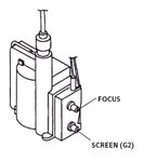
-G2(screen) voltage set too high
try to adjust the screen knob to lower the screen voltage.
sometimes if the screen voltage increases alone it could point to fly back transformer.
-RGB amplifier supply too low
it could point to the filter capacitor for that line being faulty.
 
  • Like
Reactions: ajex

    ajex

    Points: 2
    Helpful Answer Positive Rating
Thank very much mister_rf for your reply.. :-D your answer is very clear and very helpful.

Your 2nd one exactly same to my problem.

Model of the TV is Hitachi C2181MS 21" CRT TV.

Yes I checked all the capacitors and resistors in Vertical circuit, also changed the Vertical IC TDA8356.

But problem also there.

when I adjust the screen knob to lower that Horizontal line's intensity go down. when picture is very dark that lines disappear.

Now am going to replace the flyback tranformer, is it solve my problem??

thanks..
 

Try first to replace some capacitors. See RGB amplifier power supply capacitor. (22uF-47uF - 250V)
I'll try to find a schematics...
 
  • Like
Reactions: ajex

    ajex

    Points: 2
    Helpful Answer Positive Rating
See the attached schematics:
 

Attachments

  • hitachi_v2_chassis_c2045ms_tv_sm.pdf
    5.9 MB · Views: 686
If you have a normal picture with diagonal lines superimposed on it. the problem is not the scanning circuit but the blanking circuit. There is only one point being 'drawn' on the screen by each electron gun and it scans the raster left to right and top to bottom. When it reaches the end of each line or the bottom of the screen it has to move back up to the top so it can start over again. Normally, the brightness is dropped so the returning scan can't be seen, in your case it sounds like the circuit that drops the brightness is faulty. I can not see any attached schematics but there are two places to look which are most likely candidates, if there is an IC driving the video output transistors, see if it has a 'blanking' input and check the components around it. In some TVs the blanking is applied directly to the CRT so look for components on the tube base board, probably connected to the CRT control grid (nearest the cathode).

Brian.
 
  • Like
Reactions: ajex

    ajex

    Points: 2
    Helpful Answer Positive Rating
Off topic
There’s a small problem on the forum these days, you need to refresh pages multiple times to see the attached materials, (servers mirroring problems?).
ON topic
And about the capacitors in the power supply, see diagrams.
 

Attachments

  • power supply cap 1.JPG
    power supply cap 1.JPG
    157.2 KB · Views: 274
  • RGB  power supply.JPG
    RGB power supply.JPG
    87.8 KB · Views: 292
  • Like
Reactions: ajex

    ajex

    Points: 2
    Helpful Answer Positive Rating
I checked all the capacitors and resistors in RGB circuit and blanking is ok.. when I cut the blanking whole screen became white. the gap between lines in top of the screen is small and in bottom of the screen its large gap.. please help me..
this is the picture of that..
 

If you don’t have access to some ESR meter measurement system, try to replace the capacitors, otherwise it will cost you time and effort.
By the other hand, in order to help you, we need more info, so provide us additional information regarding measurement voltages in the circuit, this cover power supplies section, RGB circuit, CRT tube, vertical IC, etc.
 
Thank you mister_rf....

I'll do it and let you know the results ASAP...

Thanks again...
 

If you don’t have access to some ESR meter measurement system, try to replace the capacitors, otherwise it will cost you time and effort.
By the other hand, in order to help you, we need more info, so provide us additional information regarding measurement voltages in the circuit, this cover power supplies section, RGB circuit, CRT tube, vertical IC, etc.

I measured the voltage fly-back 190V line voltage is very low it's 45v, and H-Out transistor is not heat much.. that mean flyback problem?????

thank you..
 

It's difficult to see from your photograph but it looks like the whole picture has a green tint. This points to a fault in the green video output stage which also would account for the blanking problem.

If you can display a plain raster or failing that a channel with nothing on it, check the voltages at the collector pins of Q851, Q852 and Q853 on the tube base, they should be roughly the same.

Brian.
 
  • Like
Reactions: ajex

    ajex

    Points: 2
    Helpful Answer Positive Rating
It's difficult to see from your photograph but it looks like the whole picture has a green tint. This points to a fault in the green video output stage which also would account for the blanking problem.

If you can display a plain raster or failing that a channel with nothing on it, check the voltages at the collector pins of Q851, Q852 and Q853 on the tube base, they should be roughly the same.

Brian.

thank you betwixt.. I'll check it and see the results..

---------- Post added at 16:39 ---------- Previous post was at 16:36 ----------

It's difficult to see from your photograph but it looks like the whole picture has a green tint. This points to a fault in the green video output stage which also would account for the blanking problem.

If you can display a plain raster or failing that a channel with nothing on it, check the voltages at the collector pins of Q851, Q852 and Q853 on the tube base, they should be roughly the same.

Brian.

thank you betwixt.. I'll check it and see the results.. in previous reply I have mentioned the voltage problem, Its my mistake. the voltage is as followes

190v = 192v
95v = 94v
16v = 16.8v

Ill check that collector voltage of that RGB circuit and try to identify the falt..

Thank u again..
 

hello...

Finally I have decided to replace the flyback. But problem is still there. When I controll the screen knob to high position screen bacome white and in low position it was black(no screen). When it is in middle position picture is appear and white lines are there. And whole picture seems to little bit green color.

please help me in this.. I checked all the things that already posted here... couldn't find the solution..

Thank you..
 

That is quite normal, all you are doing is turning the whole screen brightness up and down. The fault is in the circuit that shuts the brightness down ONLY during the blanking period.

Check these components: D758 & R760, probably close to the flyback transformer.
D501 through D505 near IC201 and also confirm the voltages on Q503 are as they are marked on the schematic.

Brian.
 
  • Like
Reactions: ajex

    ajex

    Points: 2
    Helpful Answer Positive Rating
If 180v+ is good with 22uf 250v and screen shows green Retrace lines than you need to do.
1.CRT base Problem
2.Open Resistor 10k/1W on Green output Transistor
3.Green output Transistor become Leaky (Replace it)

---------- Post added at 23:23 ---------- Previous post was at 23:22 ----------

If 180v+ is good with 22uf 250v and screen shows green Retrace lines than you need to do.
1.CRT base Problem
2.Open Resistor 10k/1W on Green output Transistor
3.Green output Transistor become Leaky (Replace it)
 
  • Like
Reactions: ajex

    ajex

    Points: 2
    Helpful Answer Positive Rating
That is quite normal, all you are doing is turning the whole screen brightness up and down. The fault is in the circuit that shuts the brightness down ONLY during the blanking period.

Check these components: D758 & R760, probably close to the flyback transformer.
D501 through D505 near IC201 and also confirm the voltages on Q503 are as they are marked on the schematic.

Brian.

Hello betwixt thank you for ur reply..
I can agree with this "The fault is in the circuit that shuts the brightness down ONLY during the blanking period" But if it is happening why only few lines are shown? why all blanking lines are not shown????? I think the problem happening some blanking periods(not in all blanking periods), when I decrease brightness to very low(using screen control in flyback) this white lines disappear, But pictures are very very dark.. when I increase brightness using screen control in flyback this white lines shown and increasing the brightnes of those lines and there is a posision of screen control that whole screen became white suddenly(not slowly). then when I control RGB preset down pictures are appeared again with white lines. I feel there is a problem with blanking voltage, It may be lower than the correct voltage. please help me....

Thank you..

---------- Post added at 07:19 ---------- Previous post was at 07:17 ----------

If 180v+ is good with 22uf 250v and screen shows green Retrace lines than you need to do.
1.CRT base Problem
2.Open Resistor 10k/1W on Green output Transistor
3.Green output Transistor become Leaky (Replace it)

---------- Post added at 23:23 ---------- Previous post was at 23:22 ----------

If 180v+ is good with 22uf 250v and screen shows green Retrace lines than you need to do.
1.CRT base Problem
2.Open Resistor 10k/1W on Green output Transistor
3.Green output Transistor become Leaky (Replace it)

Thank you very much. imran green problem was solved. replaced Green output Transistor. now color is ok.. but white line problem still there.. plz help me..
 

1.Try to Control Screen volts from FBT G2
2.Replace 22uf 250v in 180v line
3.Check ABL line circuit from FBT(may be open circuit resisitor like 180k ohm)
 
  • Like
Reactions: ajex

    ajex

    Points: 2
    Helpful Answer Positive Rating
I replied yesterday but the mail was lost during the Forum update :cry:

Ajex, I'm assumuing you do not have the manufacturers IIC calibration unit so try this:

1. Turn R830 and R831 to give minimum green and blue, the picture will probably have a red tint.
2. Make a blank screen, you could try using an AV input with nothing plugged into it.
3. Make the room as dark as you can while still seeing the controls in the TV. The darker the room the better.
4. Turn the brigtness control to minimum.
5. Turn the 'screen' control on the flyback transformer until you can *only just* see the first signs of anything on the screen. It should be as close to black as possible.
6. Adjust R830 then R831 to make the picture gray. The tint will change as you turn the controls. If it starts to get brighter, turn the screen control down again. The objective is to see the darkest possible gray.
7. Display a picture again and adjust the brightness to normal level.

All of that should align the cut off points of the red, green and blue guns. If the lines are still visible let us know.

Brian.
 
  • Like
Reactions: ajex

    ajex

    Points: 2
    Helpful Answer Positive Rating
Status
Not open for further replies.

Part and Inventory Search

Welcome to EDABoard.com

Sponsor

Back
Top