Continue to Site

Welcome to EDAboard.com

Welcome to our site! EDAboard.com is an international Electronics Discussion Forum focused on EDA software, circuits, schematics, books, theory, papers, asic, pld, 8051, DSP, Network, RF, Analog Design, PCB, Service Manuals... and a whole lot more! To participate you need to register. Registration is free. Click here to register now.

How can i build circuit to sensing ac voltage by use pic microcontroller?

Status
Not open for further replies.

mohammedalnaham

Newbie level 3
Newbie level 3
Joined
May 9, 2011
Messages
3
Helped
1
Reputation
2
Reaction score
1
Trophy points
1,283
Visit site
Activity points
1,298
Any one can help me
if he can do it in proteus that is good.
I need also to code that is do this job.

Regard to every one who will help
 

This depends on what you need. You could get two things:

1) Instantaneous voltage of the AC waveform (if you captured all of the points fast enough, you could plot them and get a sinewave). This requires a sampling rate greater than the maximum AC frequency, times 2 (Nyquist criterion). I'd recommend 10*Fmax to get a more realistic capture. This also requires your analog input to be able to take negative voltages (assuming you are measuring power from something like a wall outlet).

2) You want to capture a relative magnitude of the AC waveform (if you are measuring power from the wall), then you can use a rectifier/detector circuit to make the voltage entirely positive, and the detector to strip off the AC, leaving a (mostly) DC voltage. See links below, and use them to guide you in choosing the R and C values (for wall AC, use a big C and small R, since you aren't worried about tracking high frequency amplitude modulation). Also, if using a single diode, be sure it's reverse-breakdown voltage is greater-than 2*Vpeak (if 220 Vac, then Vpeak = 220*sqrt(2) = 311 volts, and 2*Vpeak = 622 volts).

In either case, you'll probably want a voltage divider circuit, such that the voltage at the microcontroller is less than the absolute maximum voltage that the pin is rated for (see microcontroller spec sheet). Depending on how you construct your circuit, you can put the voltage divider first, then follow it with the detector, or swap them... it comes down to parts selection and some safety concerns (high-voltages present on some of the devices).

Here are a few links to articles discussing detectors.
**broken link removed**
The Envelope Detector

P.S. If using power from the wall, for goodness sake put a small, simple FUSE as the first thing in your circuit!
 

Some specs would be nice like voltage, freq source impedance.


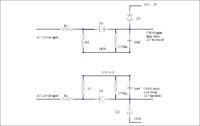
this AC voltage detector works for 60 Hz
D1 and D2 are schottky diodes
D2 protects the HC CMOS input from over and under voltage
D1 rectifies the AC
Top circuit detects the positive AC component
Bottom circuit detects the negative AC component
Ratio = 4/Vin
Voltage AC voltage detector resistor dividor
Threshold R1 R2 Ratio R2/Rt
24 100K 20K 0.167
48 100K 9.09K 0.083
72 100K 5.94 0.056
96 100K 4.32k 0.042


thanks for the post.
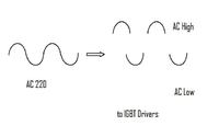
do you have a simple circuit to divide AC to AC Low & AC high.
 

thanks for all.
for this benefit information
but I ask about how can i do it simulation on Proteus using PIC MICRO-CONTROLLER 16Fxx.
mohammedalnaham
 

Status
Not open for further replies.

Part and Inventory Search

Welcome to EDABoard.com

Sponsor

Back
Top