santais
Junior Member level 1

Building a H-Bridge using PWM from a PIC16F887
Hi Guys.
I'm currently working on a school project, where we are trying to build a Line Following Robot. So far I'm able to control duty cycle of the PWM signal, with the use of 3 different sensors. So far so good. The last thing I'm missing, is to get the H-bridge working, and to be honest, I'm completely lost here.
I've tried different types of H-bridges, where I found the circuit on the internet. One of them worked, if I used the voltage from an power supply and regulated it from that. However, no success with the pic itself. Here's the transistors and other hardware, which is being used:
PIC 16F887 with a duty cycle varying from 0 - 200 (8 bit PWM. Not using 255, because of the chance to burn off the motor).
3 V DC motor x2.
2 x TIP121 and 2x TIP127 transistors.
A Power supply VDD at 5v
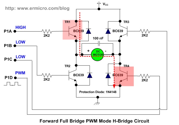
The motor has to be able to run both forward and backward. Today I tried with this setup:

However, the voltage on the pin to the motor was just high all the time, and my PWM input didn't have any effect at all.
Thanks on beforehand Hope that some of you have an idea, on how to get this running. It's an exam project, so it's quite important I get it running
Hi Guys.
I'm currently working on a school project, where we are trying to build a Line Following Robot. So far I'm able to control duty cycle of the PWM signal, with the use of 3 different sensors. So far so good. The last thing I'm missing, is to get the H-bridge working, and to be honest, I'm completely lost here.
I've tried different types of H-bridges, where I found the circuit on the internet. One of them worked, if I used the voltage from an power supply and regulated it from that. However, no success with the pic itself. Here's the transistors and other hardware, which is being used:
PIC 16F887 with a duty cycle varying from 0 - 200 (8 bit PWM. Not using 255, because of the chance to burn off the motor).
3 V DC motor x2.
2 x TIP121 and 2x TIP127 transistors.
A Power supply VDD at 5v
The motor has to be able to run both forward and backward. Today I tried with this setup:

However, the voltage on the pin to the motor was just high all the time, and my PWM input didn't have any effect at all.
Thanks on beforehand
Last edited:


