Continue to Site

Welcome to EDAboard.com

Welcome to our site! EDAboard.com is an international Electronics Discussion Forum focused on EDA software, circuits, schematics, books, theory, papers, asic, pld, 8051, DSP, Network, RF, Analog Design, PCB, Service Manuals... and a whole lot more! To participate you need to register. Registration is free. Click here to register now.

[SOLVED] LM324 opamp gain instability

Status
Not open for further replies.

kamalavignesh

Newbie level 6
Newbie level 6
Joined
Oct 4, 2010
Messages
11
Helped
0
Reputation
0
Reaction score
0
Trophy points
1,281
Location
Vijayawada
Visit site
Activity points
1,368
Hi,
I am using LM324 as inverting and non inverting amplifier for current measurement. The shunt will give 75mV@15A. This shunt output i am giving as input to LM324. I set the gain of amplifiers at fixed value but its not stable. The gain is reducing from lower end of current to higher end. I cant find why its happening. Can anyone help me?

with regards,
Kamal
 

Why don`t you enable us to give an appropriate answer based on a circuit diagram?
 

The lm324 is a pretty terrible op amp, and has very poor input and output range, especially on a single supply. Because of that, the apparent gain may vary a lot as you try to drive the outputs near their limits. Try a real rail to rail op amp and that should help. Or bias the output voltage higher.
 
Last edited:

The lm324 is a pretty terrible op amp, and has very poor input and output range, especially on a single supply.
In my opinion, it's O.K. at the negative rail, and thus LM324 is often used in simple single supply circuits. Of course the device has some limitations like class B output stage.
 

In my opinion, it's O.K. at the negative rail, and thus LM324 is often used in simple single supply circuits. Of course the device has some limitations like class B output stage.

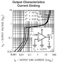
The output will never go below 0.5V unless its sourcing current. Whenever I was forced to use the 324, I would put 1K resistors from the outputs to ground so that they would be somewhat biased to do so. That was the only way I could tolerate using them.

It still blows my mind whenever I open up the control board of large power supplies and see LM324s used all over the place (usually with dual supplies though).
 

The output will never go below 0.5V unless its sourcing current.
I can't remember a similar behaviour. According to the (National) datasheet, the output swings below 10 mv at zero output current. By placing a pulldown resistor, you get down to effectively zero output voltage, so a current sense amplifier referred to negative supply can work well.

It still blows my mind whenever I open up the control board of large power supplies and see LM324s used all over the place.
Although rather old, it's still an acceptable solution for slow and medium speed applications, where inherent limitations like the class B cross-over distortions don't count. And it's really cheap.
 

I can't remember a similar behaviour. According to the (National) datasheet, the output swings below 10 mv at zero output current.
The output stage has an internal 50uA current sink for pulling it down, but even that will probably only work to 0.2V. If you're sinking more current than that 50uA, then the output can never get below 0.5V. At least it shouldn't, given the output structure, and I've never seen it happen in real life. The national datasheet I've seen has the output range specified with pull down resistors.
 

The output stage has an internal 50uA current sink for pulling it down, but even that will probably only work to 0.2V.
The purpose of the 50 uA current source is providing a bias current for Q5/Q6. It won't work at low output voltages. The 100 uA high side current source will completely flow through Q12 instead of appearing at the output.
If you're sinking more current than that 50uA, then the output can never get below 0.5V.
Yes, if the OP would be required to sink current. But it don't need to, the discussion was about sourcing a small respectively zero current.
The national datasheet I've seen has the output range specified with pull down resistors.
I'm referring to this diagram, it's exactly complying with my previous statement (and real devices behaviour as well).


P.S.: I also though about, why this old part is still frequently used. One explanation is, that senior design engineers know it from days, when it has been the only available single supply OP. They are used to it's characteristics and thus prefer it if no additional features are required.
 
Last edited:

We use the LM324 a lot for low speed current shunt applications (and the A version, and the LM 358 which is the 2 op-amp equivalent) and find the o/p goes to 5mV or below (we null the input offset), we find the limited slew rate and freq response useful as local noise is not amplified. If you do a thorough search you will not find a modern op-amp that will go as close to the 0v rail in a single supply setup, and especially not for a similar price! Regards, Orson Cart
 

Thanks for the suggestion guys. Now the gain instability problem was solved the reason for instability is due to poor wires. Now i have one more problem i connected both inverting and non inverting amplifier across same shunt to measure both charging current and discharging current of batteries.

The shunt value is 0.05 ohms and both amplifiers gain are around 6. So during charging condition i'll get the output from Non inverting amplifier and during discharging i'll get the output from inverting amplifier. The problem is upto 8A the inverting amplifier is giving the appropriate output and non inverting output is zero. But after crossing 8A current the non inverting amplifier output goes to saturation(10.25V). Can anyone help me regarding this issue?
 

One would like to see the exact circuit to understand the problem. May be one input is biased too low below the rails. A different grounding scheme can possibly help.
 

Remember lm324 input cannot swing to the positive rail, so i ll suggest the shunt resistor should be on the ground path of the battery. If this is what you have. Yet you have to know that the input cannot drop below vss-0.3. Why not upload your circuit for analysis.
 
You appear to have exceeded the -0.3 volt limit (0.05 ohms x 8 amps = -0.4 volts) on one or more of the inputs of the inverting amp... always pays to read the datasheet carefully... a smaller shunt value will help, or a divider on the input to the op-amp, Regards, Orson Cart.
 
Thank you very much orson cart for identifying the problem. Now i used 0.005 ohm shunt instead of 0.05 ohm shunt and the problem was solved.

---------- Post added at 17:25 ---------- Previous post was at 16:23 ----------

Is there any op amp was available with Vcm in the range of -0.5V to 32V.
 

Status
Not open for further replies.

Similar threads

Part and Inventory Search

Welcome to EDABoard.com

Sponsor

Back
Top