Continue to Site

Welcome to EDAboard.com

Welcome to our site! EDAboard.com is an international Electronics Discussion Forum focused on EDA software, circuits, schematics, books, theory, papers, asic, pld, 8051, DSP, Network, RF, Analog Design, PCB, Service Manuals... and a whole lot more! To participate you need to register. Registration is free. Click here to register now.

Converting a square wave into a fixed DC signal?

Status
Not open for further replies.

syee10

Member level 3
Member level 3
Joined
Apr 2, 2010
Messages
63
Helped
1
Reputation
2
Reaction score
0
Trophy points
1,286
Location
Malaysia
Visit site
Activity points
1,758
Is there any method to convert a square wave signal into a fixed DC signal? Say if i have a +1V high level and 0V low level square wave, how am i going to convert it to a DC level +1V signal? Will it works if using a low pass filter? If yes, how's the circuit looks like and what is the value of the component?
 

You can do this by rectifying the square wave with a schottky diode. Connect the anode (+) to the squre wave, and connect a small capacitor (~1nF to 100nF) to cathode for filtering. The DC voltage is measure at the cadthode. The DC voltage is close to 1V (~0.9V).
 

Could you clarify something about your question, please?
What do you mean by "a fixed DC signal" ?
Its unusual to refer to DC as a 'signal', especially if you also refer to it as 'fixed'.

If you simply mean a conversion from AC to DC where the DC voltage collapses when the AC stops, then kcyang's method may be what you are looking for, though there might be a considerable delay after the AC ceases if there is no load on the capacitor to discharge it.
 

Is there any method to convert a square wave signal into a fixed DC signal? Say if i have a +1V high level and 0V low level square wave, how am i going to convert it to a DC level +1V signal? Will it works if using a low pass filter? If yes, how's the circuit looks like and what is the value of the component?

I have done similar work before, so u could try this filter:
Low Pass Active Filter by LM741 | Circuit Project Electronic
 

You can do this by rectifying the square wave with a schottky diode. Connect the anode (+) to the squre wave, and connect a small capacitor (~1nF to 100nF) to cathode for filtering. The DC voltage is measure at the cadthode. The DC voltage is close to 1V (~0.9V).

The steady-state voltage on the cap is highly dependent on the source impedance (how much current can it supply @ 1V), and the load impedance (how much current the load is it trying to sink). If the source is high-impedance, and the load is low impedance, the load could cause the voltage at the supply to collapse to almost zero... you'd never be able to charge up the capacitor, because the load would be taking all of the energy (none left to store in the cap).
 

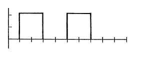
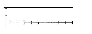
What i mean is from a square waveform (say +1V high level and 0V low level) convert to a constant +1V DC waveform as shown in the figure below
9_1301321374.png
87_1301321374.png
 

What i mean is from a square waveform (say +1V high level and 0V low level) convert to a constant +1V DC waveform as shown in the figure below
9_1301321374.png
87_1301321374.png

Understood, but you may have mitigating circumstances, depending on what is creating the 1V square wave, and was circuit you are driving the output signal into. You could use any of the above suggestions, but the results may not be ideal for some of them. The more simple approaches will have limited usefulness, but the more complex circuits could work in many situations.

Can you describe your signal source, and what device/circuit you are trying to send the output signal to? That would help us narrow it down to the "right" answer.
 

this is a pulse signal not square wave

you need to put capacitor RC >> T and then filtering stages for smoothing

but also as enjunear said .....more information is needed
 

Status
Not open for further replies.

Part and Inventory Search

Welcome to EDABoard.com

Sponsor

Back
Top