Continue to Site

Welcome to EDAboard.com

Welcome to our site! EDAboard.com is an international Electronics Discussion Forum focused on EDA software, circuits, schematics, books, theory, papers, asic, pld, 8051, DSP, Network, RF, Analog Design, PCB, Service Manuals... and a whole lot more! To participate you need to register. Registration is free. Click here to register now.

[SOLVED] is there anyway to copy the RTL synthesis schematic in ise 12 ?

Status
Not open for further replies.

blooz

Advanced Member level 2
Joined
Dec 29, 2010
Messages
560
Helped
121
Reputation
242
Reaction score
116
Trophy points
1,343
Location
India
Visit site
Activity points
4,985
Hi

is there any way to copy the synthesized RTL Schematic in another format so that it could be used for documentation purposes or else any method to export the netlist then build the schematic using some third party software .
 

Same question here. It's next to impossible to use ISE's schematics in documentation.
 

You can export the schematics as pdf, which you can then embed in your documentation. I recently posted one in this thread. Is that the sort of thing you are looking for?

With regard to the generated schematic, I wish I had a little more control of where it places what to make it more readable. But hey, it's a lot better than nothing. ;)

Other than that, I am also still looking for ways to properly document my (verilog) projects. So any suggestions?

PS: Note that the pdf in that other thread is an export from a technology view, but exporting pdf's works exactly the same way for RTL view.
 
Last edited:
How did you export that? I haven't found such a command. My only idea is to print it with a virtual printer to pdf or some graphical format.
 

How did you export that? I haven't found such a command. My only idea is to print it with a virtual printer to pdf or some graphical format.

I'll post a few screenshots in a bit.

first ... brain ... coffee ...
 

You can export the schematics as pdf, which you can then embed in your documentation. I recently posted one in this thread. Is that the sort of thing you are looking for?

With regard to the generated schematic, I wish I had a little more control of where it places what to make it more readable. But hey, it's a lot better than nothing. ;)

Other than that, I am also still looking for ways to properly document my (verilog) projects. So any suggestions?

PS: Note that the pdf in that other thread is an export from a technology view, but exporting pdf's works exactly the same way for RTL view.

yes this is one of the targets .Would you please clarify how to produce this
 

Okay, as promised some screenshots to explain things.

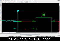
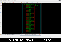
This shows the RTL schematic for this particular module:

Code:
(* REGISTER_BALANCING = "YES" *)
module bubble8_to_bin3_retimed (
    input            clk,
    input      [7:0] bubble_count_in,
    output reg [2:0] bin_count_out     // OUT: (REG) ; latency 2 (due to extra retiming register)
    );

initial begin
    bin_count_out = 0;
end

//(* REGISTER_BALANCING = "FORWARD" *) reg [7:0] bubble_count_in_retimed = 0;
reg [7:0] bubble_count_in_retimed = 0;

always @(posedge clk) begin
    bubble_count_in_retimed <= bubble_count_in;
end

always @(posedge clk) begin
//    casez(bubble_count_in)
    casez(bubble_count_in_retimed)
      // Decode RIGHT running counter
      8'b1?000000: bin_count_out <= 3'b000;
      8'b01?00000: bin_count_out <= 3'b001;
      8'b001?0000: bin_count_out <= 3'b010;
      8'b0001?000: bin_count_out <= 3'b011;
      8'b00001?00: bin_count_out <= 3'b100;
      8'b000001?0: bin_count_out <= 3'b101;
      8'b0000001?: bin_count_out <= 3'b110;
      8'b?0000001: bin_count_out <= 3'b111;
      default    : bin_count_out <= 3'b000;
    endcase // bubble_count_in
end

endmodule // bubble8_to_bin3_retimed

I'm still trying to figure out how to get register balancing to do what I want, hence some of the commented lines...

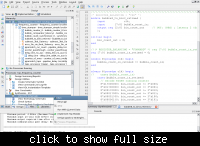
#1 Run "View RTL Schematic" from ISE Project Navigator


#2 Use the Explorer Wizard, since we want to document a specific module (as opposed to top level module)


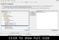
#3 Select "bubble8_to_bin3_retimed" module, and add it to the list of selected elements. Press "Create Schematics".


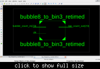
#4 Voila ... hey, that's not much of a schematic ...


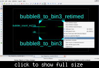
#5 Select the entire module by clicking on the outline, then do "Show Block Contents"


#6 That gives us the actual contents of the module... up close. So, press "Zoom to Full View".


#7 Okay, now there is our actual schematic. Don't worry about not being able to read things in the screenshot. The screenshot is just meant as an overview. In the pdf file things will be perfectly readable.


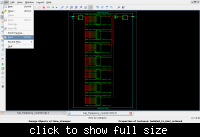
#8 Print


#9 Select "Print to File (PDF)" and print! Note that you can also print to postscript format, so you can pick whatever is easier for you to work with for your documentation. See the attachment for the output.


And that's it! This is using ISE 13.1, but worked exactly the same in ISE 12.4 a few days ago. :) And you can use this exact same method for Technology Schematics as well.
 

Attachments

  • bubble8_to_bin3_retimed-rtlview.pdf
    15.2 KB · Views: 186
Last edited:
Oh, so that's exactly what I thought. Printing to PDF is something like a cheat, I was hoping you've found some built-in fuction to export the schematics...
 

The Problem with this method is when we print to paper .the schematic get clumsy
 

Oh, so that's exactly what I thought. Printing to PDF is something like a cheat, I was hoping you've found some built-in fuction to export the schematics...

Well, you can always "export the netlist then build the schematic using some third party software". ;) If you have a working method I'm all ears!

Besides, does it matter if it's a "cheat" or not? As long as the schematic is good enough for documentation purposes then it's good enough. A .ps or .pdf is easily encapsulated to be included in documentation. The main problem I have with the ISE generated schematics is that the placement of an element is not always that great. So currently I use it because it sure beats the alternative of ... nothing.

But like I said, if you have a better alternative I would be very much interested. :)
 
Last edited:

The Problem with this method is when we print to paper .the schematic get clumsy

When you print to paper? If the layout in the attached schematic is acceptable to you, then everything else is just a matter of the right tools.

If I can get a piece of software to print to a .pdf or .ps the hard work is done. All I need to do is wrap it in an .eps (encapsulated postscript) and use that in the document...

I don't quite know what you mean by "when you print to paper". As opposed to what?
 
Last edited:

even at 100% zoom the details are not clear for larger design block ....I meant it for an A4 size paper otherwise the approach is perfect .paper size is the issue the pdf is ok.
 

Understand what you mean. However that particular issue will always remain, no matter what tool you use. Besides, you can always print that very same pdf to A3 size paper for the larger designs. If that is still too small, then I'd say some partitioning is in order. Same as with for example with electronics schematics.
 
  • Like
Reactions: blooz

    blooz

    Points: 2
    Helpful Answer Positive Rating
So I have printed the pdf with a3 size paper and it's more convenient much better than a4 .Considering to partition the schematic .Is there any graphics editor that allows smooth partition of the pdf ? that is some software that can divide the picture in to a3 sized sheets .
 

So I have printed the pdf with a3 size paper and it's more convenient much better than a4 .Considering to partition the schematic .Is there any graphics editor that allows smooth partition of the pdf ? that is some software that can divide the picture in to a3 sized sheets .


Well, for multipage printing like that I would use "psnup" under linux.

But what meant by partitioning is more like ... make sure you have only so much information per page to prevent clutter. You don't have to print out the entire design on one page. ;) Which is why I said same as with electronics schematics. You don't put the entire schematic of an entire design on 1 page. You split it into manageable chunks.
 
  • Like
Reactions: blooz

    blooz

    Points: 2
    Helpful Answer Positive Rating
Multipage printing is a good solution .it works .for larger design I am using multipage printing with a3 sheets
 

Status
Not open for further replies.

Part and Inventory Search

Welcome to EDABoard.com

Sponsor

Back
Top