o_0
Member level 3

Hi,
The attached code has three 1-axis accelerometers sending data to an Atmega32, which interfaces with the PS/2 port of the computer. I have some questions about this:
(1) At the beginning of the code:
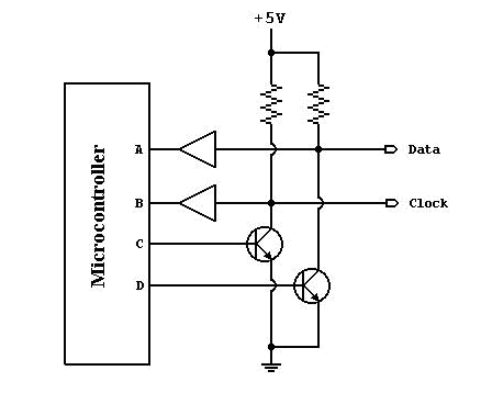
I'd like to know how this relates to the following diagram of an open-collector interface. In the diagram, what do A, B, C, and D mean in terms of CLK_OUT, DATA_OUT, etc? C and D don't connect to the computer at all?
(2) Also, in the code I'm trying to figure out what pins take the accelerometer inputs. I would much appreciate it if someone could please enlighten me regarding this as well as pointing out the part of the code that says it. Thanks in advance.
The attached code has three 1-axis accelerometers sending data to an Atmega32, which interfaces with the PS/2 port of the computer. I have some questions about this:
(1) At the beginning of the code:
#define CLK_OUT PORTC.1
#define DATA_OUT PORTC.6
#define CLK_IN PINC.3
#define DATA_IN PINC.4
I'd like to know how this relates to the following diagram of an open-collector interface. In the diagram, what do A, B, C, and D mean in terms of CLK_OUT, DATA_OUT, etc? C and D don't connect to the computer at all?
(2) Also, in the code I'm trying to figure out what pins take the accelerometer inputs. I would much appreciate it if someone could please enlighten me regarding this as well as pointing out the part of the code that says it. Thanks in advance.


