assassin10000
Newbie level 3

- Joined
- Nov 22, 2010
- Messages
- 3
- Helped
- 0
- Reputation
- 0
- Reaction score
- 0
- Trophy points
- 1,281
- Activity points
- 1,320
I'm trying to figure out how to modify the tachometer circuit in my car to accept the signal from an aftermarket standalone ECU. Unfortunately I DON'T have enough electronics knowledge/background to figure this out first time through on my own  . Help would be much appreciated.
If you want to see my original thread about this on the car forum where I originally was seeking an answer, its here:
Using AE86 Tachometer & Aftermarket ECU 12v output? - Toymods Car Club
From what I understand, the original circuit is triggered off the positive voltage spike that occurs when the ignition coil fires. The 'input' of the tachometer circuit is connected to the negative side of the coil. I believe the spike could be up to 20-40v. The circuit as I understand it, is a frequency to voltage type, moving the tachometer motor to display RPM on a scale depending on the voltage derived from the input frequency (galvanometer?).
The aftermarket ECU has a 12v output, and is NOT enough to trigger the tachometer circuit. I tried it.
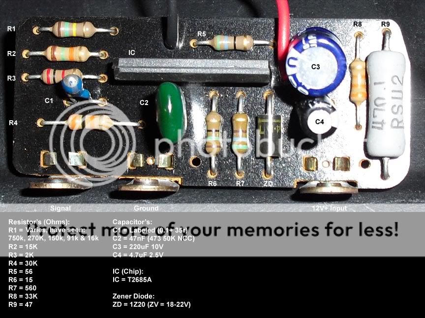
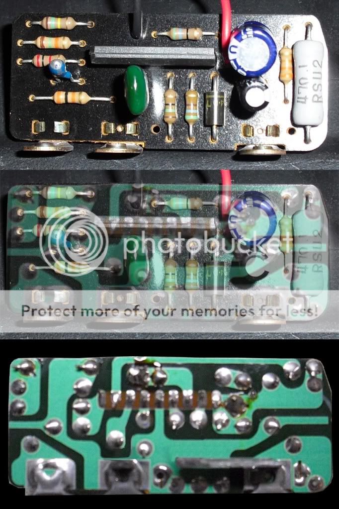
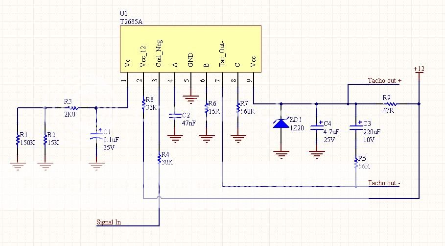
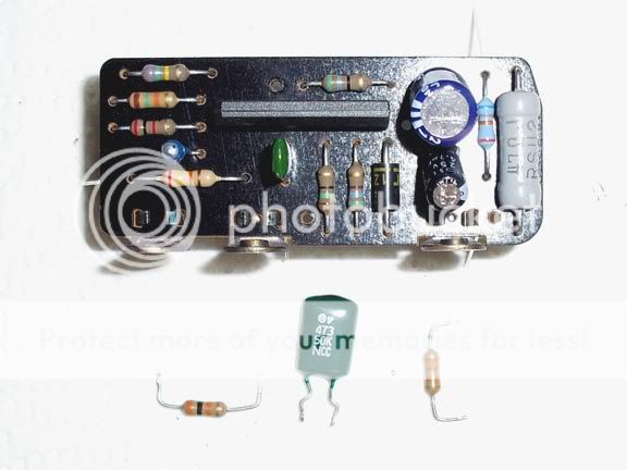
I pulled the circuit board itself and another guy was kind enough to draw up a diagram for me. Here's a few pics, identifying the components, the physical circuit board and the circuit diagram.


Now, I've found out that this circuit board was used on several different engine/ecu's with BOTH 4 & 6 cylinder engines, which would have different 'frequency' counts due to the number of cylinders fired per rotation. And with both 'high' (20-40v) and low (12v) signals, depending on if it had a distributor with a single coil or coil packs.
I also found this, which outlines what other guys have done to modify the tach input signal:
**broken link removed**
Anyways, here's what I'm thinking needs to be done.
A) based on the other tachometers I've run across change:
C2 to '472' (4700pf)
C4 to 33uF 25V
R4 to 15K
R8 to 39K
B) follow the PDF and change
C2 to '472' (4700pf)
R4 to 24K
R8 to 68K
Now, to quote myself here's what I 'think' the breakdown of differences are after looking at several different tachometer circuits. And this is what I based the changes for option 'A' on. Feel free to skip the 'quoted' part below this if you are able to understand the circuit diagram and can help me with what needs to be changed.
If you want to see my original thread about this on the car forum where I originally was seeking an answer, its here:
Using AE86 Tachometer & Aftermarket ECU 12v output? - Toymods Car Club
From what I understand, the original circuit is triggered off the positive voltage spike that occurs when the ignition coil fires. The 'input' of the tachometer circuit is connected to the negative side of the coil. I believe the spike could be up to 20-40v. The circuit as I understand it, is a frequency to voltage type, moving the tachometer motor to display RPM on a scale depending on the voltage derived from the input frequency (galvanometer?).
The aftermarket ECU has a 12v output, and is NOT enough to trigger the tachometer circuit. I tried it.
I pulled the circuit board itself and another guy was kind enough to draw up a diagram for me. Here's a few pics, identifying the components, the physical circuit board and the circuit diagram.


Now, I've found out that this circuit board was used on several different engine/ecu's with BOTH 4 & 6 cylinder engines, which would have different 'frequency' counts due to the number of cylinders fired per rotation. And with both 'high' (20-40v) and low (12v) signals, depending on if it had a distributor with a single coil or coil packs.
I also found this, which outlines what other guys have done to modify the tach input signal:
**broken link removed**
Anyways, here's what I'm thinking needs to be done.
A) based on the other tachometers I've run across change:
C2 to '472' (4700pf)
C4 to 33uF 25V
R4 to 15K
R8 to 39K
B) follow the PDF and change
C2 to '472' (4700pf)
R4 to 24K
R8 to 68K
Now, to quote myself here's what I 'think' the breakdown of differences are after looking at several different tachometer circuits. And this is what I based the changes for option 'A' on. Feel free to skip the 'quoted' part below this if you are able to understand the circuit diagram and can help me with what needs to be changed.
Moving on to some new (to me) info, and trying to draw some more conclusions on my own. I've found out that the 7mge/7mgte/1jzgte (and probably several other toyota's) use the same circuit board and IC for their tachometers.
This is what I'm thinking, based on the info I've read:
1. The 7mge is the same voltage 'level' of signal as the 4age. As it has a distributor w/ignitor firing a single coil and gets it's signal from the coil negative like the 4age.
2. 7mgte/1jzgte/2jzgte is the same/similar input to the 4agze w/coil packs. These three seem to run the 7mgte 'turbo model' tach's fine, which is supposed to be receiving a 12v signal.
Well, besides the fact it has a different pulse/frequency count because of 6 vs 4 cyl.
Reference pics/links:
**broken link removed**
(note: on the above page R5 mislabelled as 55 ohm, looking closely it appears to be a 56 ohm)
**broken link removed**
**broken link removed**
Comparing components on the few pictures 'found' in the various threads (see links/pics above). Starting with resistors:
R5 = 56
R6 = 15
R7 = 560
R9 = 47K
Resistors 5-7 & 9 are the same for 4age/4agze/7mge/7mgte/1jzgte. So obviously no changes necessary here...
R1 = 7mge #1 62k & #2 180k, 7mgte 130k and 1jzgte 100k
It appears that R1 varies on both 7mge tachs also. Which I think supports my 'guess' that it varies to adjust accuracy of each tach to their drive motor.
R2 = 12k 7mge/7mgte/1jzgte.
R3 = 510 7mge | 560 7mgte & 1jzgte
Compared to the 4age/4agze tachs, r2 & r3 are different. I'm guessing R2/R3 is also affecting accuracy, after all they are on a different tachometer. R2 stays the same, and R3 close to the same when compared between the different 6 cyl versions. Why that is I don't know, but when comparing what little info I can find on 4age vs 4agze, R3 stays the same and R1/R2 are different, for what appears to me to be a different gauge/sweep. (IF anyone reading this has a 4agze cluster, please take a high res pic and identify the components on it.)
I do know some of toyota's tach's had a variable resistor (or two) on them which would allow accuracy to be adjusted for both range/reading and different pulse counts. So R3 'could' be one thing that is changed to either; 'read' a 6 cyl pulse vs a 4 cyl, and/or another sweep/range adjustment.
R4 = 30k 7mge | 15k 7mgte/1jzgte
This is the first one that I think I will be changing/experimenting with. On the 7mge it's the same as 4age. And the 7mgte/1jzgte motors all change to what appears to be the same value as what I've found so far for the 4agze.
R8 = 33k 7mge | 39k 7mgte/1jzgte
The second to be changed/experimented with. Again, 7mge same as 4age. And the 7mgte/1jzgte is again the same as I saw listed for the 4agze.
Moving onto the capacitors:
C1 = N/A 7mge | 0.1+ 35v, 7mgte/1jzgte.
It wasn't identified positively on the 7mge, but appears identical. Most likely it's the same, so no change here.
C2 = N/A 7mge | .0047uF 7mgte/1jzgte. It's actually labelled "472 50K NCC".
Again, it wasn't identified for the 7mge. But looking at the pic's, physically it appears closer to being the same 473, found on the 4age board than the ones shown for the 7mgte/1jzgte tach's. This is another one I will experiment with.
C3 = 47uF 10V 7mge/7mgte/1jzgte..
Probably has to do with 6 cyl vs 4 cyl signal, as the 4age/4agze which both are 220uF
C4 = 4.7uF 25V 7mge, 33uF 25V 7mgte/1jzgte
Another I will experiment with, as the 7mge once again matches the 4age. And changes for the lower level signal of the 7mgte/1jzgte (which is the same as whats shown for the 4agze).
