Continue to Site

Welcome to EDAboard.com

Welcome to our site! EDAboard.com is an international Electronics Discussion Forum focused on EDA software, circuits, schematics, books, theory, papers, asic, pld, 8051, DSP, Network, RF, Analog Design, PCB, Service Manuals... and a whole lot more! To participate you need to register. Registration is free. Click here to register now.

Help to choose ESR meter

Status
Not open for further replies.

brosskgm

Member level 4
Member level 4
Joined
Dec 9, 2010
Messages
76
Helped
2
Reputation
4
Reaction score
2
Trophy points
1,288
Location
California, USA
Visit site
Activity points
1,853
I'm a new student (53) taking electronics repair again to refresh from 20 years ago. Things have changed a lot since then. 6 of us had decided to build our own equipment. I have successfully built a Capacitance meter, Diode, Transistor tester, Blue Ring tester with my own project pcb not kit purchased.

But I have been having a tough time to build an ESR meter to work when finished. Either because of needed parts not available in US are very costly, or minimums making a $30 project cost $118 or not having a pic programmer and so on. With two failures and deciding not to investing any more kit's or DIY projects for the ESR meter, I have to ask what one of the following or other recommended in the same price range would be a good choice and will be able to advance with me as I pursue this new career.

I'm looking for someone that has either used one of the following or the one they recommend to answer. chuckey/Frank please don't respond. Your not helping the question.

I'm not at a level to design my own circuits, just learning to repair them. Can read schematics enough to be totally dangerous and find my way around the board. The Blue ESR is $30 more than the Canada one and they are both + shipping but seem to be the same. But since I'm not sure I'm hoping for help and guidence here.

I've seen this one on eBay

h**p://cgi.ebay.com/In-Circuit-Capacitor-ESR-Meter-Digital-ESR-Tester-/280605758923?pt=LH_DefaultDomain_2&hash=item41556815cb

Or the Blue ESR

h**p://www.anatekcorp.com/blueesr.htm

Thank you so much.
Bob
 
Last edited:

hi,
I just think you'd better buy a cheap pic programmer (search for pickit2 on ebay they start à $30)
and then build a pic based esr meter, they are the best today
like this russian open source one :

**broken link removed**

source here :
**broken link removed**
(google translator is a good help ...)

full package :
**broken link removed**
 

I looked at that one, but didn't what know .spl, .lay, .a16 files were. Windows wouldn't open them.

In the states the pickit2 is $40 and up. Then the parts for the ESR $40 - $118 (That I have already priced, tried) some of the parts needed were not available here with out costing more or taking three weeks to get here. Some times you can find the one piece you need but there is $15 - $20 just to ship one part. mouser (Local supplier in CA) doesn't have everything but is always $20 to ship. I even ordered an esr kit for $60 from over seas, took three weeks to get here but never really worked as it should. With the PIC programmer just for the ESR meter, I might never use it again or very little.
 
Last edited:

.spl is for SPlan, .lay is for Sprint Layout
they are both available free as reader here :
Demo versions
you then only need the .hex file to program the pic
you can make a much cheaper pic programmer : a jdm programmer.
IC-Prog Prototype Programmer, programs : PIC16F818, 16F819, 16F630, 16F676, 12C508, 16C84, 16F84, PIC 16F877, 24C16, 24C32, 93C46, 90S1200, 59C11, 89C2051, 89S53, 250x0, PIC, AVR , 80C51 etc.

by the way I think today having a pic programmer and an avr programmer available is not a waste of money ...
there are so many projects made with them...

you can also ask in a local components store there are surely in california, if someone can program the pic for you for some bucks...

---------- Post added at 10:46 ---------- Previous post was at 10:40 ----------

just had a search on ebay : pickit2 are aven cheaper than ever ...

**broken link removed**

---------- Post added at 10:55 ---------- Previous post was at 10:46 ----------

another way is to build an analog esr meter.
I successfully build this one a long time ago, and it still works with "drawers components" ...
 
I'll look at Sprint, SPlan software again. When it said demo software it usally means 30 days.

---------- Post added at 05:59 ---------- Previous post was at 05:24 ----------

At the ic-prog web site they had the ID multi Ziff programmer. It uses a LPT port?, if 25pin serial, I don't have serial on my system. It just mentiones Type "D"
I could not find the jdm you mentioned.

---------- Post added at 06:03 ---------- Previous post was at 05:59 ----------

Never mind. The Ziff one is not going to work. It doesn't program any of the 16F87's
 

SPrint Layout only disables saving after 30 days. it let's you print other's files indefinitely.
-------
the pic can use ISCP in circuit serial programming.
you need 4 wires: v- gnd pgc pgd
you will with that program almost any pic
the program you use will do the work, not the interface.
I can assure you I programmed 16f87x with a jdm ...
the jdm cannot program certain pics that have a precise timing for MCLR (very recent ones)
and of course you need a serial interface... if you only have a parallel interface, I can't help you I didn't use it for pic programming I don't know the best...
 

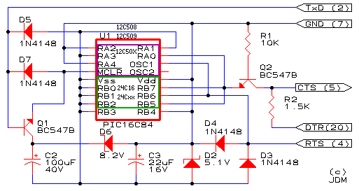
this is jdm (or ludipipo)
Jdm-v22.gif
 
it is to show where the pic (or the 24xx eeprom) goes.

another with-no-pic esr meter, still a digital one, from the german elv:
 

Attachments

  • ELV ESR1_KM_G_021017.pdf
    369.9 KB · Views: 324
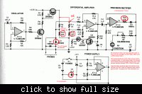
this is another "with-no-pic" esr meter
this one is connected to a standard multimeter to display the result
 

Attachments

  • esr meter silicon chip.jpg
    esr meter silicon chip.jpg
    67.2 KB · Views: 479
I saw that one, and actually liked it but it used a lot of SMD that I have not tried yet and not having anything to translate. I've seen the other showing.

---------- Post added at 11:13 ---------- Previous post was at 11:09 ----------

That has a pic on it that would need to be programmed right?
 

there is no pic in the elv esr meter. the circuit is a standard 7106 display circuit... may be more difficult (and more expensive) to find nowadays than a basic pic ...
 

ICL7106 is between $3 - $5 ea + $4 - $12 shipping here in the states. I would hope I could find someone that already built it or if someone knows how to read it and answer a few questions.

1.) why 4 +9v points, 2 +5v points and 2 +2.5v points.
2.) Then not understanding schematics enough there are a lot of areas where they just end. Is that ground?
3.) How long are the test leads? This seemed to be a problem in one. When they were longer than 30 cm it was hard to zero it with out error. That's a bit short 11 inches.

---------- Post added at 12:11 ---------- Previous post was at 12:10 ----------

But I have to not think about this one for now. It's double sided. and a bunch of SMD on the bottom and would have to have the PCB made.
 

Here is the write up and how to calibrate information.
Silicon Chip Online - Circuit Notebook

Basically, the circuit generates a low-voltage 100kHz test signal, which is applied to the capacitor via a pair of probes. An op amp then amplifies the voltage dropped across the capacitor’s series resistance and this can be displayed on a standard multimeter.

In more detail, inverter IC1d is configured as a 200kHz oscillator. Its output drives a 4027 J-K flipflop, which divides the oscillator signal in half to ensure an equal mark/space ratio.

Two elements of a 4066 quad bilateral switch (IC3c & IC3d) are alternately switched on by the complementary outputs of the J-K flipflop. One switch input (pin 11) is connected to +5V, whereas the other (pin 8) is connected to -5V. The outputs (pins 9 & 10) of these two switches are connected together, with the result being a ±5V 100kHz square wave.

Series resistance is included to current-limit the signal before it is applied to the capacitor under test via a pair of test probes. Diodes D1 and D2 limit the signal swing and protect the 4066 outputs in case the capacitor is charged.

A second pair of leads sense the signal developed across the probe tips. Once again, the signal is limited by diodes (D3 & D4) before begin applied to the remaining two inputs of the 4066 switch (pins 2 & 3 of IC3a & IC3b). These switches direct alternate half cycles to two 1μF capacitors, removing most of the AC component of the signal and providing a simple "sample and hold" mechanism.

The 1μF capacitors charge to a DC level that is proportional to the test capacitor’s ESR. This is differentially amplified by op amp IC4 so that it can be displayed on a digital multimeter – 10Ω will be represented by 100mV, 1Ω by 10mV, etc.

To calibrate the circuit, first adjust VR1 to obtain 100kHz at TP3. Next, momentarily short the test probes together and adjust VR4 for 0mV at pin 6 of IC4.

That done, set your meter to read milliamps and connect it between TP4 and the negative (-) DMM output. Apply -5V to TP2 and note the current flow, which should be around 2.1mA. Transfer the -5V from TP2 to TP1 and adjust VR2 until the same current (ignore sign) is obtained. Remove the -5V from TP1.

Again, set to your meter to read volts and connect it to the DMM outputs. Apply the probes to a 10W resistor and adjust VR3 for a reading of 100mV.

Finally, ensure that all capacitors to be tested are always fully discharged before connecting the probes.

Len Cox,

Forest Hill, Vic.


this is another "with-no-pic" esr meter
this one is connected to a standard multimeter to display the result


---------- Post added at 19:06 ---------- Previous post was at 19:00 ----------

I almost forgot. They only list the voltage for one Cap 100uf 16v, does that mean the rest are also 16v and the rest non polarized that are not labled?

this is another "with-no-pic" esr meter
this one is connected to a standard multimeter to display the result
 

This is great! the second one link is not working. (view result on a multimeter or a vu-meter) Is there any layouts for these or .sch files that can be imported to eagle to make a layout? Most the houses that can do boards need the eagle, Gerber, cad files to work from.

Thaks so much.
 

Status
Not open for further replies.

Part and Inventory Search

Welcome to EDABoard.com

Sponsor

Back
Top