Continue to Site

Welcome to EDAboard.com

Welcome to our site! EDAboard.com is an international Electronics Discussion Forum focused on EDA software, circuits, schematics, books, theory, papers, asic, pld, 8051, DSP, Network, RF, Analog Design, PCB, Service Manuals... and a whole lot more! To participate you need to register. Registration is free. Click here to register now.

What's the function of SG3524 IC in an inverter circuit?

Status
Not open for further replies.

jerkymotion

Member level 4
Member level 4
Joined
Oct 12, 2010
Messages
73
Helped
28
Reputation
56
Reaction score
28
Trophy points
1,298
Location
NEPAL
Activity points
1,824
hi every one..
i found this IC...SG3524... on my inverter..which i bought from the market..
i have read the datasheet but could not find the reason behind this IC to be used in inverter.circuit ...my inverter is 50watt...
anyone please can you explain how this IC works..
every help will be appreciated
 

Re: SMPS control circuit

I'd think the TI dataSheet explains it rather well, incl. appropriate application info.
 
  • Like
Reactions: ghewarlal

    V

    Points: 2
    Helpful Answer Positive Rating

    ghewarlal

    Points: 2
    Helpful Answer Positive Rating
Re: SMPS control circuit

Hi,
Well, this is a PWM chip. For understanding PWM:
**broken link removed** ---------> I recommend this
Pulse Width Modulation
Introduction to Pulse Width Modulation (PWM) | Netrino

Okay then, first get your head straight with PWM and how it works and then go through the datasheet:
focus.ti.com/lit/ds/symlink/sg3524.pdf

If then you still don't understand, you'll find many here to help you.

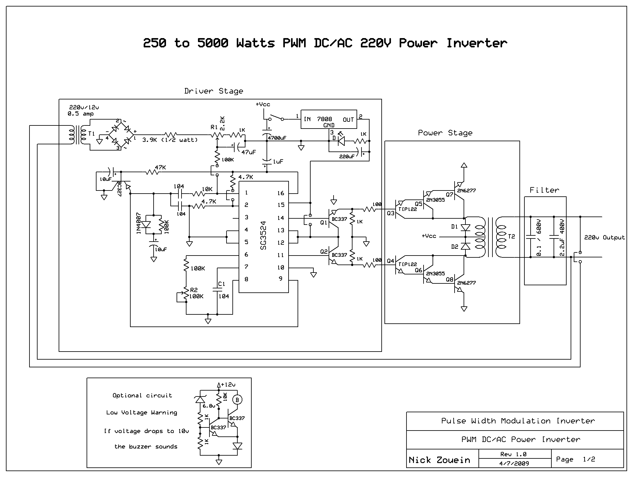
Take this as reference:
49_1251563341.gif


Hope this helps.
Tahmid.
 
  • Like
Reactions: jerkymotion

    jerkymotion

    Points: 2
    Helpful Answer Positive Rating
    V

    Points: 2
    Helpful Answer Positive Rating
Re: SMPS control circuit

Mr Tahmid,i want get 100 khz frekuensi using sg 3524,so we using the formula,but when i make it on pcb and i test and measure with osciloscope,i dont get the frekuensi that i expected

please help me...
 

Re: SMPS control circuit

The 3524 has unity gain bandwidth 3MHz and the transition times ON+OFF are 0.3usecs .As such you cannot expect to go beyond 33KHZ as you shall need a min gain of 100 for your drives.
The supply is 12VDC max. and the pushpull drives at transformer give saturation drops of approx.1VDC for the swing.As such ferrite winding ratio Pri::sec is 1:10 for getting 220VAC
However , the 3stage Darlington drive pushpull stages can be bettered by using Low Rdon MOSFET like STW80N06 which is 60V/80Amp /Rdson =0.01 ohm.
 

Re: SMPS control circuit

Hi,
Well, this is a PWM chip. For understanding PWM:
**broken link removed** ---------> I recommend this
Pulse Width Modulation
Introduction to Pulse Width Modulation (PWM) | Netrino

Okay then, first get your head straight with PWM and how it works and then go through the datasheet:
focus.ti.com/lit/ds/symlink/sg3524.pdf

If then you still don't understand, you'll find many here to help you.

Take this as reference:
49_1251563341.gif


Hope this helps.
Tahmid.
can u help me out with d pbc layer of dis schematic

---------- Post added at 17:16 ---------- Previous post was at 17:14 ----------

Hi,
Well, this is a PWM chip. For understanding PWM:
**broken link removed** ---------> I recommend this
Pulse Width Modulation
Introduction to Pulse Width Modulation (PWM) | Netrino

Okay then, first get your head straight with PWM and how it works and then go through the datasheet:
focus.ti.com/lit/ds/symlink/sg3524.pdf

If then you still don't understand, you'll find many here to help you.

Take this as reference:
49_1251563341.gif


Hope this helps.
Tahmid.
can u help me out with d pbc layer of dis schematic
 

mr tahmid i have built this circuit of pwm invertor which you have posted i have problem that it is not oscillatin i only get voltage at only one output some time i get on pin14 and pin 11 has no voltage and if i turn off i get voltage at pin 11 and no signal at pin 14 please help what to do
 

can we obtain variable frequencies using SG3254??
 

good morning every one,please,mr tahmid i am a child in sg3524,i followed ur blogs on this but not been able to find any,d only one i saw with detailed explanation was sg3525,pls am in need of the functions of all these pins,if u have worked with that before can u help me post the blog address so i can read through,i enjoy that 4 sg3525 (self explanatory)
 

hey guys need help..i just want to ask, is it possible that using IC sg3524 can have an output of 10 hz frequency and how can i achieve it.
 

Mr tamid could we design a sine wave inverter circuit using the sg3524 as part of the circuit. Thank u
 

Status
Not open for further replies.

Similar threads

Part and Inventory Search

Welcome to EDABoard.com

Sponsor

Back
Top