Continue to Site

Welcome to EDAboard.com

Welcome to our site! EDAboard.com is an international Electronics Discussion Forum focused on EDA software, circuits, schematics, books, theory, papers, asic, pld, 8051, DSP, Network, RF, Analog Design, PCB, Service Manuals... and a whole lot more! To participate you need to register. Registration is free. Click here to register now.

[SOLVED] Diagram of an active crowbar circuit for overvoltage protection

Status
Not open for further replies.

kalaianand

Advanced Member level 4
Full Member level 1
Joined
Jun 17, 2010
Messages
113
Helped
11
Reputation
22
Reaction score
10
Trophy points
1,298
Activity points
2,025
hi friends
If anybody have circuit diagram for the active crowbar circuit for overvoltage protection. please provide the circuit diagram. i understood the crowbar circuit diagram function. but while reading i come to know about the active crowbar circuit which have good advantage, (no blowing of fuse). please suggest your ideas
 

Active crowbar

Hi,
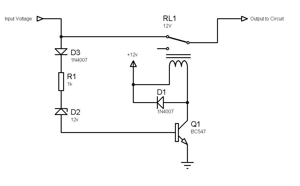
Here is a circuit, which I think should serve the purpose. The active crowbar here is relay based, although it is possible to make it solid-state depending on your power requirements.
The crowbar "trip" voltage is Vzener + Vdiode + Vtransistor = Vzener + 0.7v + 0.7v = Vzener + 1.4v
So, in this circuit, Vzener = 12v, therefore trip voltage is approximately 13.4v

98_1277451560.jpg


Hope this helps.
Tahmid.
 
  • Like
Reactions: bulgaa

    bulgaa

    Points: 2
    Helpful Answer Positive Rating
Re: Active crowbar

Thank u tahmid
really it is usefull to me. How to impletement the same without relay? do we need seperate isolation supply to operate switching semiconductor? and the transister is working here is common base mode know?
really thankfull to dear friend
 

Active crowbar

Hi,
This works in common emitter mode.
Without relay, you can use BJT or MOSFET, with or without isolation supply, depending on circuit configuration.

Hope this helps.
Tahmid.
 

Re: Active crowbar

hi tahmid
Thank u for your reply
how this is common emiter mode, here the transister is biasing through base know, so its common base mode, right!! correct me if i am mistake...
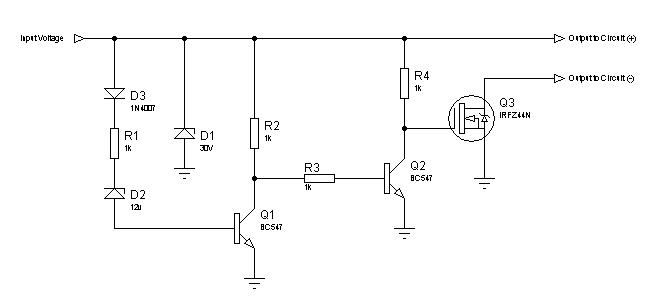
can u please provide me the circuit diagram which does the same function without relay!( using Mosfet).
 

Active crowbar

Hi kalaianand,
I think you should read these two articles, and then maybe you will be clear about things:

en.wikipedia.org/wiki/Common_emitter
en.wikipedia.org/wiki/Common_base

Hope this helps.
Tahmid.
 

    kalaianand

    Points: 2
    Helpful Answer Positive Rating
Re: Active crowbar

hi tahmid
thank u, i understood the logic. can u please provide me the active crowbar circuit configuration using switching device(without using relay). in my apllication 4Amp current flows through the relay, so drop is increasing. i want to minimize the losses, i need the same circuit using switching device, without using islation supply


thank u
 

Status
Not open for further replies.

Similar threads

Part and Inventory Search

Welcome to EDABoard.com

Sponsor

Back
Top