Continue to Site

Welcome to EDAboard.com

Welcome to our site! EDAboard.com is an international Electronics Discussion Forum focused on EDA software, circuits, schematics, books, theory, papers, asic, pld, 8051, DSP, Network, RF, Analog Design, PCB, Service Manuals... and a whole lot more! To participate you need to register. Registration is free. Click here to register now.

how to make vpulse modulation in pspice

Status
Not open for further replies.

qais_abdulkareem

Newbie level 4
Newbie level 4
Joined
Feb 21, 2010
Messages
7
Helped
0
Reputation
0
Reaction score
0
Trophy points
1,281
Location
jordan
Activity points
1,329
good day all...could any one give me the parameters for vpulse in pspice..i want to apply it on diode clamped inverter...exactly on 3-level diode clamped inverter...what is the parameters and on which switch i need to apply this vpulse?...thankx in advance
 

Not sure of the Pspice syntax, but Hspice is

Vxxx n+ n- PU<LSE> <(>v1 v2 <td <tr <tf <pw <per>>>>> <)>

where:

Vxxx, Ixxx Independent voltage source which will exhibit the
pulse response.
PULSE Keyword for a pulsed time-varying source. The
short form is ‘PU’.
v1 Initial value of the voltage or current, before the
pulse onset (units of volts or amps).
v2 Pulse plateau value (units of volts or amps).
td Delay time in seconds from the beginning of
transient interval to the first onset ramp.
Default=0.0 and negative values are considered as
zero.
tr Duration of the onset ramp in seconds, from the
initial value to the pulse plateau value (reverse
transit time). Default=TSTEP).
tf Duration of the recovery ramp in seconds, from the
pulse plateau back to the initial value (forward
transit time). Default=TSTEP.
pw Pulse width (the width of the plateau portion of the
pulse) in seconds. Default=TSTEP.
per Pulse repetition period in seconds.
Default=TSTEP

Keith.
 

i am really so thankfull to your kindness keith ..i actually ment in my question the values for each parameter because i have a 3-level diode clamped inverter that i need to apply modulation on it...i am starting with this vpulse and i think i am entering wrong values of these parameters...that is why i want the values...then i will think where to apply the modulator on which switches...hope you may help ...in anyways i am so thankfull to you...if i could contact you through email to send you my circuit then that will be gr8...thanx
 

dear can i have your email adress to send you my circuit pls. because i dont know how to send here on this site cus i am new as i told you ..i have yahoo email: time_search@yahoo.com

Added after 11 minutes:

hi...attached the cct and i like to send it software to you if u may help ..but i need to send it to your email ..here i dont know how
thanx


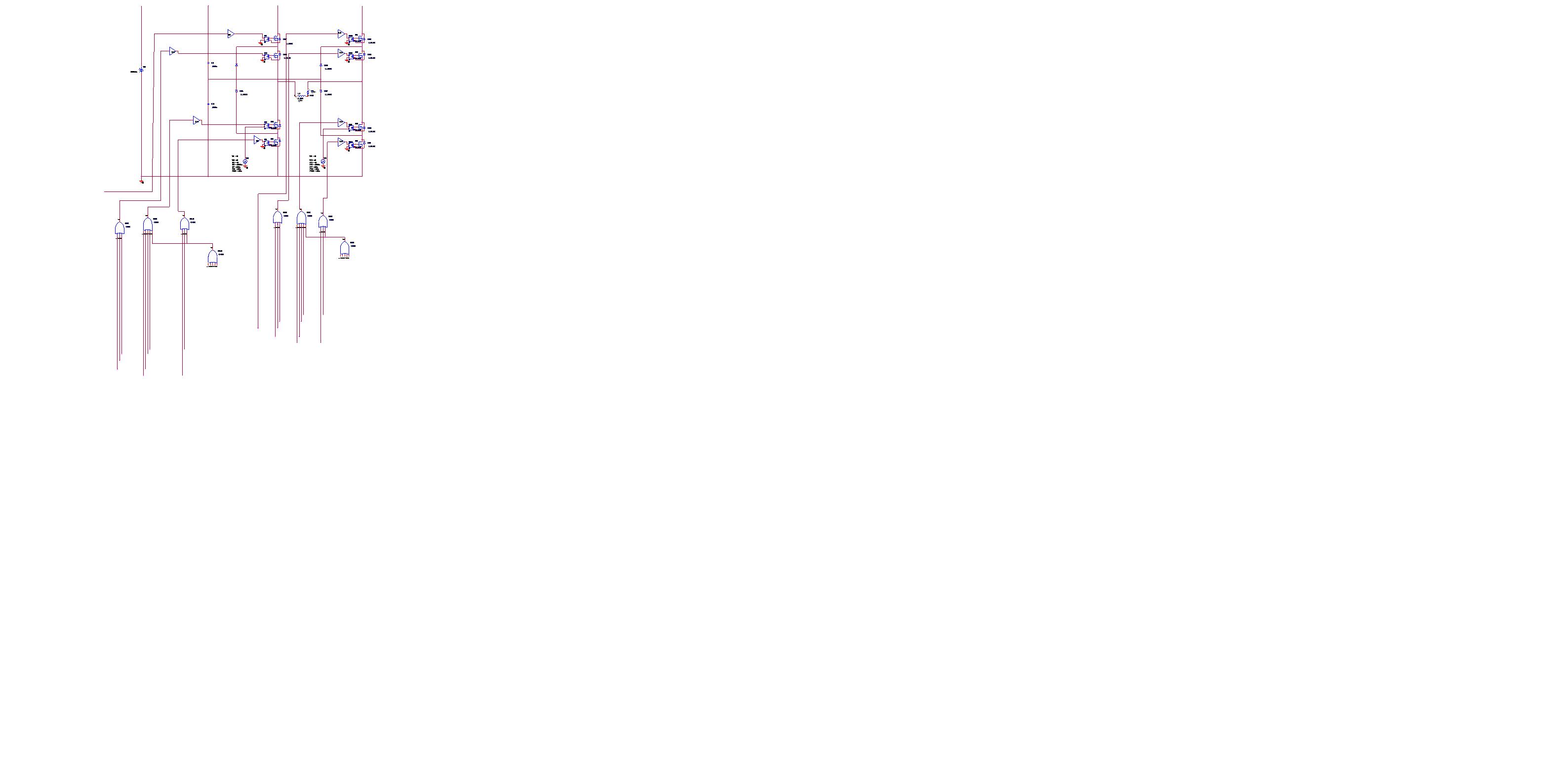
this is attached the cct wid the modulator and it has a good response but not that ok because the values of vpulse parameters are maybe not well choosen..
url=http://obrazki.elektroda.pl/48_1267041505.jpg]
48_1267041505_thumb.jpg
[/url]

48_1267041505.jpg
 

hi
hope u r doing fine
i found the first problem in my cct as i send the picture of it 4 u..it was the wrong location of vpulse entering the and gate with the digital cct that controls the switches...instead i put vpulse as another input for mosfet and it works better...but i have problem...for entering only R-load the response shape is ok but when entering L- load the response is not ok...could u pla help...thanx
more over may i have ur personal email to send u my cct on pspice...thanx and wishes
 

Status
Not open for further replies.

Similar threads

Part and Inventory Search

Welcome to EDABoard.com

Sponsor

Back
Top