Continue to Site

Welcome to EDAboard.com

Welcome to our site! EDAboard.com is an international Electronics Discussion Forum focused on EDA software, circuits, schematics, books, theory, papers, asic, pld, 8051, DSP, Network, RF, Analog Design, PCB, Service Manuals... and a whole lot more! To participate you need to register. Registration is free. Click here to register now.

connecting ULN2003a with relay to drive 24vDC light

Status
Not open for further replies.

irshad.khn

Newbie level 4
Newbie level 4
Joined
Sep 24, 2009
Messages
6
Helped
1
Reputation
2
Reaction score
1
Trophy points
1,283
Location
Bangalore, INDIA
Visit site
Activity points
1,331
Hi,

I have a PIC micro which i want to connect to a 24v 1A DC light (bunch of LEDs packed into one big light), I know i can use a relay and ULN2003a and 24v supply to do the things, but I am not understanding how to connect them together. Please help me with the connections. A schematic would be of more help.

Thanks in advance
 

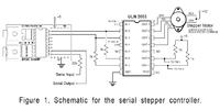
I'm not sure what a stepper motor driver has to do with a light controller.

Connect the PIC to any THREE inputs of the ULN2003 (linked together), connect the ground pin of the ULN2003 to the negative or ground side of your supply. Then link the THREE outputs corresponding to the input pins you used together and connect them to the cathode (-V) side of your light. Leave the other ULN pins disconnected.

The reason for using three parallel drivers in the ULN2003 is that each is only rated at 0.5A. Two would be pushing the current demand to the limit, three gives you a safety margin.

Brian.
 

As "betwixt" wrote, you may connect the inputs and the outputs of the ULN and then drive the 1amp load or if you choose to use a relay, you may follow the attached schematic. But for using just one relay you may consider using just one NPN transistor instead using the ULN. Cheers
 

    irshad.khn

    Points: 2
    Helpful Answer Positive Rating
Thanks "pranam77" and "betwixt" for the reply. It works for me, but i would like to know whether this type of setup is safe or not i.e, will it fry my PIC because of high current requirement of the load?

BTW I need to drive 3 such lights so I am using ULN instead of transistors.

Also, do I need 3 relays or is there some alternative?
 

Three single darlington power transistors is probably the best solution. The ULN2003 and it's big brother the ULN2803 are just current switches with logic level inputs. They can be considered to be an array of 7 or 8 medium current darlingtons which you would parallel together to make one high current one.

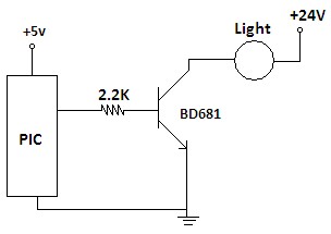
The simplest and cheapest solution would be to use three NPN darlingtons, rated at 2A or more (BD681 or similar). Connect the emitter pin to ground, the light to the collector pin and feed the base from the PIC via a 2.2KΩ resistor. One transistor is used in each of the three light circuits you want to switch, you wouldn't need the ULN2003 at all this way.

The load current from the PIC would only be around 0.4mA and the light circuit could switch anything up to 4 Amps.

Brian.
 

betwixt,its amazing to read your explanations.i'm also a person who is looking for the same thing wat irshad is doing except the controller because am not yet clear wat setup am asked for.
i would be really thankful if you could suggest based on the below articles which i'm bought to make a led to glow.
1)2 tap transformers
2)4 optocouplers(mct6)
3)CD4053(DIP),74HC14(SOIC)
4)CD4543B
5)ULN2003A

these are the above am asked to use to burn an common anode led 7 seg display.how should i proceed.schematic would be really gud along with the usage of the IC's which am using.please help me.
 

Hi Brian.

I have used BD681 and connected lights, the logic is correct and the circuit works. But the problem is that each of the transistors dissipate approx 38Watts of power (as heat) which is too much.

Please suggest how I can deal with this issue?
 

irshad.khn said:
I have used BD681 and connected lights, the logic is correct and the circuit works. But the problem is that each of the transistors dissipate approx 38Watts of power (as heat) which is too much. Please suggest how I can deal with this issue?
It is quite common to generate heat when the transistor is loaded.
You may reduce the load which will reduce the heat generated by the transistor. OR
You may use a suitable heatsink like PI48 Or PI49 OR
You may use some other transistor like MJE3055 or SD313 with better current handling capacity. Cheers
 

BD681 has a maximum VCEsat at 1.5A of 2.5V.

Your design carries 1A so it will be less than 2.5V.

Where does the 38W figure come from, at 1A and taking a pessimistic rating of 2.5V in saturation, the power dissipated is only 2.5W.

Brian.
 

32_1255534453.jpg


I have connected the light as shown in the schematic, is this correct? The light has a knob which if I increase to max, it draws 1.5A-1.7A of current and it increases the intensity of light.

The BD168 becomes very hot, it cannot be touched. My bread board got melted!

If I mount this on the PCB containing PIC will it not dissipate the heat to other components and cause damage? Is using heat sink only solution?

Can a relay be used along with this? How can I connect it? I have 10A/24VDC(5vDC coil) relay.

Thanks
Irshad
 

A heat sink is probably the simplest solution but there are other methods. If you use relays you will waste power in the relay coil and they tend to be physically big. Consider that a relay and heat sink would probably be about the same size but the relay less efficient.

The underlying problem is the voltage drop across the transistor. The power it dissipates is the Collector to Emitter voltage multiplied by the Emitter current. There isn't much you can do about the current because your lamp needs it to function so the only realistic way to reduce the heat is to drop less voltage across the transistor.

There are many solutions but these are probably simplest:

1. Instead of using a darlington transistor, use a normal small power transistor and connect a second transistor to boost the base current. Connect the 2.2K to the base of the new transistor, connect its emitter to the base of the power transistor. The collector goes to the 24V supply through a resistor. Choose the resistor value so it lets enough current flow to saturate the power transistor. Something in the region of 680 to 820 Ohms will probably do. This method only adds two components, the new transistor and it's collector resistor.

2. Use a power MOSFET instead of the BD681. These devices will drop much lower voltages, typically less than 0.2V per Amp. The drawback is that you may need more voltage than the PIC can supply to turn it fully on. Look for "logic level" MOSFETS, you should be able to find something suitable, otherwise you need a second transistor again to act as a gate voltage booster.

Sorry I can't draw diagrams at the moment, due to family problems I am not at my usual PC until next week.

Brian.
 

Could you please give me one or two part numbers of power MOSFETs. Also explain me how the connections differ from BD681?

Added after 7 minutes:

Actually, I had developed a working prototype with ULN2003A and relay. The reason i switched to transistor instead of ULN is that the ULN2003A needs +12V supply which is not available. I have only 24VDC.
 

I am not at my data sheets at the moment to find out part numbers but if you Google for "logic level MOSFET" it should find something.

The ULN2003A does not require a power supply, it is only an array of current sinking transistors. If you are referring to the 'common' pin, it is the junction of clamp diodes on all the outputs. The 2003A will 'work' from about 1V up to 50V.

Brian.
 

i am using uln2804 to drive a relay 12v...
i have connected one terminal of relay to fix 12v and the other to uln... the question is would it work if i supply logic 1 to the uln...

i assume that when i would supply logic 1 it would turn the relay on... the connections are same as in pic except instesd of 24vdc i m using 12vdc...

but it doesnt work.. what could be the prblem?


Added after 2 minutes:

also i have tried to check it on breadboard... connecting in the same fashion and appliying both ground and 5v to the pin 1turn by turn.... nothing happens............
 

It should work fine.

The ULN2804 is he same as the ULN2803 except it needs slightly higher logic 1 voltage to turn it on. Make sure you have the correct pin numbers, they are not the same as in your diagram. There is one extra driver stage in the 2803/4 that isn't in the 2003 so the pins are rearranged slightly. Your connections should be:

Logic input = pin 1
Relay output = pin 18
Ground = pin 9
Clamp diode (COM) = pin 10.

Brian.
 

Status
Not open for further replies.

Similar threads

Part and Inventory Search

Welcome to EDABoard.com

Sponsor

Back
Top