Aggiemundo
Newbie level 5

measure voltage through insulated wire
I'm an AC idiot so I could use some help as I try to better myself. I am trying to build a low cost, low power circuit that will detect when an AC voltage is passing through a set of wires, and then blink an LED to indicate this. I don't want to tap into the AC wires, but want to sense that voltage is flowing through them through induction.
I have taken an unsheilded wall cable hooked to a lamp and coiled a wire around it ten times. My o-scope is showing a nice 4Vpeak AC signal being induced into my wire. However, when I try to pass that through a bridge rectifier (or even a single diode for a half-bridge) I see the same AC wave output as is input to the diode. What am I overlooking here?
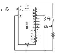
To give you an overview of what I'm trying to do, for the LED flasher I'm just going to use a simple flasher circuit and AA battery as shown here:
**broken link removed**
I believe that if I tie the oscillator circuit into one node of an AND gate, and then tie the other node of the AND gate into my AC current sensing circuit which would be high or low based on an AC current passing through the main wire.
Thanks for any advice (or backhands) you can give!


