Continue to Site

Welcome to EDAboard.com

Welcome to our site! EDAboard.com is an international Electronics Discussion Forum focused on EDA software, circuits, schematics, books, theory, papers, asic, pld, 8051, DSP, Network, RF, Analog Design, PCB, Service Manuals... and a whole lot more! To participate you need to register. Registration is free. Click here to register now.

Coin counter using pic16f877a

Status
Not open for further replies.

riversky2k17

Newbie level 4
Newbie level 4
Joined
Nov 22, 2017
Messages
5
Helped
0
Reputation
0
Reaction score
0
Trophy points
1
Visit site
Activity points
71
Hello everyone!!!

I have a project: COIN COUNTER using PIC16f877a.
I need help to get the output pulse of the coin to the T0CKI of the MCU and display the output on 4-digit 7 segment LED.
I already have idea on how to display the output on the 7 segment since I tested burning programs (like incrementing counter, led flashing) on the chip and got them work.
I programmed the coin acceptor (CH-926) to recognize 5 type of Philippine coin (10cents, 25cents, 1peso, 5peso, 10peso).
The coin acceptor (CH-926) provides varying pulse for each coin type of coin: (I checked using multimeter coz I dont have oscilloscope).
10cents=5pulses (change in voltage per second).
25cents=8pulses
1 peso=12pulses
5 peso=15pulses
10peso=18pulses
The range of voltage (DC) for the various types of coins is 2.68 to 4.29v. The voltage did not drop from 2.68 and did not go higher than 4.29v for each type of coin.
I am using a pic development board, mplab ide 4.05 + xc8 compiler, and proteus for simulation.
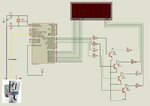
See attached image for my project setup. jacksparrowxx.jpg
 

Re: coin counter using pic16f877a

It seems strange that the voltage is different for each type of coin. Are you measuring it on an oscilloscope or a DVM? If you are using a conventional voltmeter it will not show the true voltage if it is pulsed but it will show a higher voltage if there are more pulses. It may be that the pulses are at 12V in which case you need to limit it to VCC or the PIC may be damaged.

If you are intending to measure the voltage, you must use an ADC input, not the timer input. However, a better solution would be to use the delay between one coin and the next to reset a pulse counter then count the pulses until the next reset. For example, if the coins were inserted no quicker than one per second:
1. has one second elapsed since the last coin?
2. no - so keep the counter active
3. yes - use the pulse count to identify the last coin then go to step 1.

Brian.
 

Re: coin counter using pic16f877a

thank you sir for the quick reply, I am using DVM to measure voltage. the coin acceptor outputs a constant 4.29v when no coin is inserted. when a coin is inserted, the voltage decrement every second down to 2.68v and back up to 4.29v for each pulse duration stated (5 pulses for 10cents). I dont know if it's the correct way to measure the output voltage/pulse, but i dont have any type of visual meter, i am only using my digital multimeter.
 

Re: coin counter using pic16f877a

You can't use a DVM in that way. A DVM takes samples of the voltage at repeated times and shows the average of several measurements. The times used will vary from one model to another. If the average includes times when the pulse is high and times when it is low, the average will be different but you will not know the peak or lowest voltage. However, if it reads 4.29V when there are no pulses, it suggests it has a TTL level output which probably really changes from 4.29 to about 0.5V for all the pulses.

If you find the longer delay between coins it should identify where the pulses from one coin and the next start and stop so you can use that to count how many coins and how many pulses each produces.

Basically, you need two counters, one counting the coin pulses and the other counting time, maybe in 1mS intervals. Every time a pulse arrives you reset the time counter to zero and if it ever reaches say 100mS you assume there are no more pulses from that coin so you use the pulse count from that coin to identify it and start looking for any more coins. I'm guessing at the time limit, it should be about 25% longer than the time it takes to send pulses for the largest coin. The specification for the coin unit should tell you the pulse rate.

Brian.
 

Im sorry sir, but I am a developer doing mostly vbstudio projects and this is my first time doing a PIC programming. I just tried yesterday with using the K150 pic programmer and successfully done with the counter and flashing led. Would you be so kind sir to show me an example of C code that counts coin pulses and the one you said for counting time using pic16f877a. or maybe a good link with reference to the PIC 16f877a, I've been searching the internet for reference but most are done in Arduino, and the others using other PIC, others posted only the actual setup but no sample code. I dont need the full working code but a reference. I learned programming this way, learning on my own with the help of the internet. I know electronics (a subject - during my college days) but not that knowledgeable.
 

There are many references to using the timers on the internet but without a specification for the pulses it is impossible to write code to count them. Do you have the full data on the coin machine that shows the timing of the pulses and the gap between successive coins?

Brian.
 

Hi,

Usually those pulses are sveral 100ms in time.
Use a LED to make the pulses visible.
Maybe take video and play it in slow motion.

Klaus
 

[merged] multiple pulse input to pic16f877a

Hi fellow!

I have attached an image of 2 options for my input setup.
My questions are...
1. Which is possible to use, Setup 1 or Setup 2 to receive 6 input for pic16f877a.
2. How can i determine which input is active or turned on (like a press on a push button) in a fraction of second so that i can determine what to display on my 7 segment. Can I use only one timer to determine interrupt? Can you show me a sample code in C. I am using MPLAB + XC8 compiler and proteus for simulation.

Existing Setup/Conditions:

1. I am using pic16f877a mcu
2. Each pulse does not exceed 4v (tested using dvm) but i dont know the duration and width.

I have already idea on how to do the display part. I also tested using interrupts and timers.
 

sir Brian..

The coin machine that I have dont have information on the output pulse. It only came with information regarding its pin connections and how to set it up for recognizing coins. I've been searching the net since I created this post but no results up to this writing.

Because of this im thinking of doing the other way around. I have observed that whenever a coin is inserted and is successfully recognized, a LED on the coin acceptor blinks. There are 6 leds for the 6 types of coins it can recognize. I'm thinking of wiring each LED connection directly to my pic mcu as inputs. and with these I'll just program the mcu to determine which led blinks. Can I wire the 6 connection to the 6 pins on RB (0-5)? and let timer and interrupt do the recognition. RC and RD are already setup for 7 segment display.

I 've done testing 1 input using interrupt and timer but i dont know how to do it with 2 or more. Can you show me a sample in C.

I attached an image of my setup in Proteus.
 

Re: multiple pulse input to pic16f877a

Hi,

There's no attachment.

Klaus

- - - Updated - - -

Hi,

First you need clean signals. If they are generated from any mechanical contact, then add a debouncing circuit.
Then please define the timing of the signal. How fast do you need to react on a signal. One edge only (like a counter) or do you need to detect both edges?
You say you don't know duration and width of the pulse...This is a "no go"! This is like writing an eMail, but not knowing the address of the receiver. Find it out somehow. Measure it, read datasheets, or define "meaningful" pulse values on your own. Especially when you want some valuable response then you give such informations. We don't know if you are talking about ps, ns, us, ms, s ...values

Then it isn't clear to me:
* are you talking about one signal that can generate 6 pulses
* are you talking about 6 individual signals? If so: Is it possible that some signals are active at the same time?

How to safely detect signals:
* either by "interrupt on pin change"
* or by polling the pin state

Polling: you need to poll with a frequency more than twice your pulse frequency.
With a human operated switch I recommend to poll about every 20ms.
This is not difficult: just set up a time so it generates an interrupt every 20ms. The read the input state(s) and perform some urgent functions. This depends on your needs...what information you want to gain from the signal. Set flags for the main loop. Don't do heavy calculations. Don't use busy waits. The ISR should be as short in time as possible. Then leave the ISR.

Do the heavy processing in the main loop.

This polling function should not take more than 1% of your processing power...even if it is performed every 20ms.

Update your display max 4 times per second ... faster update can't be processed by the brain.
(You may do this with the same 20ms ISR...just every 16th ISR run..or similar)

*****
Don't expect that anybody writes the code for you, this is not how a forum works.

*****
"You have an idea"
Then show us. Show us what you have done so far. This motivates users to respond to your post.
Users can verify your work and can optimize it. This is how a forum is meant to work.

Klaus
 

Status
Not open for further replies.

Similar threads

Part and Inventory Search

Welcome to EDABoard.com

Sponsor

Back
Top