welove8051
Full Member level 6

- Joined
- Jul 16, 2009
- Messages
- 357
- Helped
- 51
- Reputation
- 102
- Reaction score
- 41
- Trophy points
- 1,308
- Location
- india
- Activity points
- 3,277
hello all, i am working on a hardware project, which simulates a DC motor, that is, a hardware circuit replaces a DC motor and performs the function of DC motor. in the equivalent circuit of a DC motor back emf(V_emf) is represented by a voltage source. the back emf depends on load. the real DC motor operates on several amps of (load)current. when i realize the back emf circuit, i am not sure how to design it, so that it can with stand 40amps of load current.
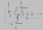
circuit explanation: motor_+ motor_- is the motor terminal input.
L1, R6 equates DC motor coil and resistance.
R1 for series current measurement
M1,M2,M3 controlled by controller based on current. M2 for rush current and M3,M1 for load current.
EMF_S+ is the voltage source. through PWM required voltage can be generated. the voltage comes from a regulator.
is this design correct? how to design/safe guard the back emf regulator from the high load current coming from the motor driver circuit.
kindly suggest how this concept can be realized.
refer this post for DC motor current.
thanks in advance


