Continue to Site

Welcome to EDAboard.com

Welcome to our site! EDAboard.com is an international Electronics Discussion Forum focused on EDA software, circuits, schematics, books, theory, papers, asic, pld, 8051, DSP, Network, RF, Analog Design, PCB, Service Manuals... and a whole lot more! To participate you need to register. Registration is free. Click here to register now.

Ambient light noise (sunlight & Fluorescent lamps) in photodetector

Status
Not open for further replies.

JamesGon

Junior Member level 1
Joined
Sep 8, 2017
Messages
18
Helped
0
Reputation
0
Reaction score
0
Trophy points
1
Visit site
Activity points
157
Hi

I am trying to estimate the shot-noise from ambient light sources (sunlight and Fluorescent lamps).
I expect to shield my photodiode as good as possible - so no direct light is hitting it.
Second, what is the relationship between photodiode area size and noise from ambient light - is it proportional like: Id(shot-current) = Area*responsivity*irradiance.


Thank you.
 

Hi,

Shot noise should be caused by the semiconductor of the photodiode. It should be independent of light source.
You need to measure the current, not the voltage. An amplifier will introduce additional noise.

The light source will be noisy, too. But I have no values.
I assume the noise of sunlight is very low.
But for sure if you run an FFT on sunlight intensity on earth you will get two major frequency spots:
* 1/day
* 1/year
* i assume there will be a third one: 1/week, caused by pollution
The rest of it will be very random, mainly cased by clouds.
I don't expect much high frequency noise.

For flourecscent light the dominant frequencies will be much higher..it depends on how the driving voltage is generated.
I'd say it is impossible to give a general answer on this.

Klaus
 

Light sources don't involve shot noise, received photons and charge carriers in a photo detector however do.

Respectively you get a certain amount of shot noise produced in the photo detector which is not originated from intensity fluctuation of the optical source. Although SNR is increasing with light intensity, the absolute noise level is still increasing with square root of intensity. In so far a high level of constant ambient light affects the measurement of a small AC signal.

Fluorescent lamps have strong 100/120 Hz and in case of inverter operated devices also multi 10 kHz components that can be quite problematic for all applications using modulated light. Sunlight has almost clean continuous intensity.
 

Okay, thank u.
Sorry – for not be being precise, I meant the shot-noise (from the photodiode) generated by the ambient light ��.
I have been trying to calculate the shot-noise current. I found out that room lighting is approximately 500 lux – which corresponds to 3-5 Watts/m^2.
With a photodiode active area of 0.5mm^2 – The shot-noise Id is 1.5µA (using the eq. Area*responsivity(0.6)*irradiance.).
This number sounds quite big in my ear – this is of course without any shielding.
 

Basically as calculated in your previous post, light intensity multiply diode sensitivity. Spectral light intensity and diode sensitivity curve must be considered however.

Unless you have an exactly defined exposition scenario, it's probably easier to measure the actual diode current with a reference setup.
 
Okay thank you.

I am using TIA for a current to voltage conversion. The photocurrent is 600nA, the question is therefore should I use an input (in series with the photodiode) resistor to get Vin (how big should this resistor be)– since the gain is A = Vout/Vin?
The input signal is modulated (the LED) with 600 Hz square wave with a duty on 1% - this gives a frequency of 60KHz. How do I decide the following parameters 1. The gain A 2) The Bandwidth 3) Settling time (how is this affect by the duty-cycle)
 

Hi,

confusing.

With a TIA usually the voltage across the photodiode is constant.
And with a TIA your formula "A = Vout/Vin" is not valid.

The input signal is modulated (the LED) with 600 Hz square wave with a duty on 1% - this gives a frequency of 60KHz
This statement makes no sense to me.

Gain of a TIA is given in V per A = V/A

Bandwidth of a TIA is determined by the feedback resistor and the feedback capacitor. fc = 1/ (2 x Pi x R x C)
Settling time depends on OPAMP - and the cutoff frequency fc. and is not affected by the duty cycle.

Klaus
 

Series resistor makes no sense for TIA.
The input signal is modulated (the LED) with 600 Hz square wave with a duty on 1% - this gives a frequency of 60KHz.

I guess you want to estimate the useful signal bandwidth. 60 kHz gives at least an order of magnitude for an amplifier bandwidth required to reconstruct the input waveform. The useful bandwidth depends however on the signal detector properties. You need to specify the detection algorithm to determine an optimal bandwidth related to best SNR.
 

Hmm. I am not quite sure, I am understanding you. My 3db cutoff (bandwidth) should be at least 60 KHz (fp) Right?
Using the eq. fp = 1/(2pi*CF*RF). Which parameters should I tweak on. I know Cf creates a pole that counteracts the zero from beta, but how should I chose Rf. (Voutmax-Voutmin/Idmax)?.
For choosing an appropriate amplifier, I should calculate the Gain bandwidth product – fGBW = Cin+CF/2piRfCF^2 right?.
I am also confused about how I should chose my open loop Gain? The current signal is 600nA.
 

Hi,

My 3db cutoff (bandwidth) should be at least 60 KHz (fp) Right?
We don't know.
You give informations piece by piece therefore after each post we another situation.

Which parameters should I tweak on
First calculate Rf, since it is the gain factor. Rf = Vout / Iin
Then calculate Cf according your desired cutoff frequency.

GBW of the amplifier needs to be higher than your desired fc. I recommend at least ten times.

Why you want to calculate open loop gain?
Do you want to use the amplifier in open loop?
What is it good for?
At which frequency? It is about GBW / f.

Klaus
 

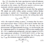
EqSettlingtime.PNG

Okay, Super. With the settling time vs duty-cycle. I found this eq. Cd is the output capacitance of the photodiode, epilson is the settling accuracy, A is the open-loop gain. D is the duty-cycle.
Have anybody seen these equations before, why does the settling time depend on the open loop gain? eq (14). And how does the duty-cycle and switching frequency come into the picture in eq.15?
Thank you.
 

Hi,

sadly you posted only a snippet of a document... therefore it´s rather difficult to verify if it complies or not.

Cd is the output capacitance of the photodiode
In my eyes the photodiode capacitance plays not a big role when the photodiode is connected to a TIA.
The TIA just compensates the photodiode current to zero at the inverting input node of the TIA.
This means the voltage is kept constant. With a constant voltage there is no current in a capacitance. No current means no influence.
This is true for an ideal TIA.

And the big benefit of the TIA circuit is, that the photodiode capacitance has (about) no influence on the signal bandwidth.

If Cd really is the photodiode capacitance, then I don´t think that R is the feedback resistor.

Klaus
 

Are you sure?
The doc is attached.
 

Attachments

  • Trade-off for low power.pdf
    516.2 KB · Views: 136

CircuitG.PNG


The transimpedance doesn’t present a small impedance, because a Gain error signal Vo/AOL remains across the diode and its capacitances, which gives us the time constant: RfCD/(AoL).. See attached picture.
 

Hi,

I´ve had a look through the document.
So indeed R is the feedback resistor.. but it´s divided by the open loop gain of the amplifier, therefore R/A becomes very small.
This is a consideration of a real amplifier and not an ideal amplifier.
Sadly they don´t put a schematic or at least drafts in the document, where it becomes more clearely what he is writing about.

Let´s do some calculations:
So assuming you have a photodiode with about 70pF and you want a cutoff frequency of 60kHz
let´s calculate an imaginary input TIA input R:
fc = 1/2 x Pi x R x C
R = 1 / 2 x Pi x R x fc = 38 kOhms

Now if you want a feedback resitor of 1Mohms, then you need an amplifier with an open loop gain higher than:
1 MOhms / 38 kOhms = 26.5 at 60kHz
26.5 = 28dB at 60kHz

Klaus
 
Ah okay. So it basically puts a requirement to my open-loop gain.

I have calculated my resistor to be 12Mohm ( Voutmax (5V)-Vmin(0.1V)/Inmax (400nA)).

(2) Then I calculate the Feedback capacitor fc=1/(2pi*Cf*Rf) at 60kHz, which gives 221fF. (to obtain stability)

(3) Then I calculate fz =1/(2pi(Cin+Cf)*Rf) (the zero), where Cin = Cphotodiode(11pf)+Camplifer (10pf), I am rewriting this to get the desired resistor R = 1/(2pi(Cin+Cf)*fc = 84.961KOhm. (By the way isn’t the 3db cutoff decided by eq. 2?, and why didn't you include Cf in your procedure? )

So my open loop gain should be 12MOhm/84.961KOhm 43dB. In the datasheet, they usually put the AOL gain with a specific resistor like at 10kOhm the open loop gain is 132 db. How should I read these numbers?

(4) I calculate the GBW= Cin+Cf/(2piRfC^2)

- Thank you
 

Status
Not open for further replies.

Part and Inventory Search

Welcome to EDABoard.com

Sponsor

Back
Top