Continue to Site

Welcome to EDAboard.com

Welcome to our site! EDAboard.com is an international Electronics Discussion Forum focused on EDA software, circuits, schematics, books, theory, papers, asic, pld, 8051, DSP, Network, RF, Analog Design, PCB, Service Manuals... and a whole lot more! To participate you need to register. Registration is free. Click here to register now.

Isolated probe for inverter measurements needed?

Status
Not open for further replies.

Akshaydpal

Member level 1
Member level 1
Joined
Feb 23, 2017
Messages
35
Helped
0
Reputation
0
Reaction score
0
Trophy points
6
Visit site
Activity points
284
HI ,
i have DSO TBS2072b from tektronics (ground is not isolated )
will the DSO will get damage if i check mosfet oputput without using isolated probe (using normal probe).??
Actually i am buying this oscilloscope so during demo the marketing team told me about this so i am confused coz i never herd of such things before . Or is it just just there marketing trick to sell me an isolated probe as well?
 
Last edited by a moderator:

Mains supplied oscilloscopes like TBS2072 have the ground tied to protective earth. Respectively you must not connect the probe ground to a mains supplied inverter without isolation transformer.

High voltage differential probes are a standard tool of power electronics development. You can get less expensive types from third parties.
 
what is this isolation transformer??
can u please explain with the help of a diagram on how to use isolation tranformer while testing mosfert output with normal probe.

thanks in advance for your help
 
Last edited:

If your circuit is battery-powered so no problems at all, you can measure freely. If your circuit uses isolated power supply (i.e. power adapter with 2 pins for mains and a trasformer inside), again no restrictions. But if your power supply connects 0V rail (GND) to protective earth (PE), you can connect alligator clips of the probe ONLY to 0V rail in your circuit. But you're still able to check your circuit (mosfet) and can measure voltage relative to 0V rail. If in this case you try to connect the alligator clip to a point that has a potential other than 0V, you'll make low-resistance path with non-zero voltage that may lead to disasterous results because of large current.
 
At work, we use some very expensive LeCroy diff probes.

At my home lab, I use the much less expensive ProbeMaster 4232

They have many models, depending on your budget and your requirements.

https://probemaster.com/differential-probes/
 
You can use a 220V/220V isolation transformer with 100W power. You may get this from any small term transformer manufacturer.
 

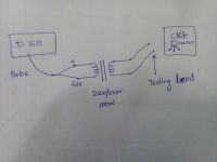
if i use 220/220v isolation transformer with 100W power. the connections will be like ine side of transformer will be connected to probe + and gnd . and the other side will serve as testing points . Then no need to worry about connections gets accidently reversed ?? I hope this is what u ment .

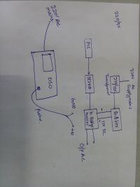
Image is attached as per my understanding


https://obrazki.elektroda.pl/2401855700_1492407904.jpg
 

The schematic seems to connect the isolation transformer between the device under test and the oscilloscope probe. This won't work for the intended purpose and will in case of doubt damage the device under test.

The suggestion was to isolate the inverter power supply.

There's also a theoretical option to isolate the oscilloscope supply, but it involves a hazardous contact voltage at the oscilloscope case and controls and thus can't be suggested.
 
then how am i suppose to use isolation transformer please help me . it would be great if u prove me with a pictorial example.
 

An isolation transformer has a plug, which you connect to the wall outlet; and a connector which you connect to the device under test.

Check for instance: **broken link removed**

NOTE: I'm not promoting this product or vendor. I only used it as an example, because it has good images.
 
An isolation transformer has a plug, which you connect to the wall outlet; and a connector which you connect to the device under test.

Check for instance: **broken link removed**
.

but i did not understand how to use this while testing an inverter circuit if possible can you please elaborate using an image
 

Very simple:
Instead of connecting the inverter directly to your wall outlet, connect it first to the isolation transformer.
Then connect the isolation transformer to the wall outlet.

In plain English, the isolation transformer will be between the wall outlet and the device you are testing.
 

but inverter im testing will be powered by the battery

You should have started by telling us this in the first place.

If the inverter is ONLY powered from the battery, and NOT CONNECTED IN ANY WAY to the AC mains or physical GROUND, then it is effectively floating.
You don't require an isolation transformer.
 
It depends. Grounding a circuit node through the probe ground clip can affect circuit operation in different ways, even if it's isolated. If you e.g. ground a bridge output node to measure high side transistor Vgs or Vds, you superimpose a high frequent common AC voltage to the complete inverter which may cause all kind of problems.
 
Status
Not open for further replies.

Similar threads

Part and Inventory Search

Welcome to EDABoard.com

Sponsor

Back
Top