Continue to Site

Welcome to EDAboard.com

Welcome to our site! EDAboard.com is an international Electronics Discussion Forum focused on EDA software, circuits, schematics, books, theory, papers, asic, pld, 8051, DSP, Network, RF, Analog Design, PCB, Service Manuals... and a whole lot more! To participate you need to register. Registration is free. Click here to register now.

3 Phase 4 Wire Connection for L&T Whole Current Meter

Status
Not open for further replies.

Sanath Embedded

Member level 3
Member level 3
Joined
Jan 23, 2009
Messages
57
Helped
4
Reputation
8
Reaction score
3
Trophy points
1,288
Visit site
Activity points
1,676
energy meter connection

Hi Guys,

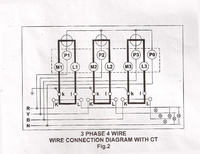
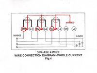
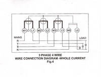
Currently I am working with Three phase Four Wire connection for Whole Current Meter. But as I refereed the L&T Metering manual for the input & Load terminal connections for the whole current meter it looks something different as shown in diagram.
Phase (R,Y,B,N) have been given to (M1, M2, M3, M0) terminals respectively and the Load connections ( L1, L2, L3) have been given to one end of the Load and Neutral connection given to the other end of the load. But I am not able to understand the connection from M1, M2,M3 which all been shorted to Neutral.Please help me out to clarify the things.
 

three phase energy meter connection

Hai Sanath Embedded
I dont see any short between the Live and Newtral. You have to just connect the R Y B and Neutral to M1, M2, M3 and M0 and connect the 3 phase load wires and Neutral to L1, L2, L# and L0 respectively. It is clear. Don't see anything above the connecting terminals in the circuit given. Those circuits represent circuits inside the meter. Helped??? Good luck
 

l&t energy meter

Hi pranam

As you said Input phase terminals are connected to M1, M2, M3 and M0 and the load terminals to L1, L2, L3 and L0. But still in the meter circuit I wonder what is the need of shorting M1, M2, M3 terminals with Neutral line.Here Phase lines (R,Y,B) are given to the Current Transformer (CT) and other end given to the Load terminal. So the CT o/p will be connected to the Meter circuit.

Regards
Sanath
 

whole current meter

But still in the meter circuit I wonder what is the need of shorting M1, M2, M3 terminals with Neutral line.
They aren't shorted. The circles with crossed lines represent the power respectively energy metering circuit.
 

energy meter connections

Yes my reply will be the same as FvM. It is not shorted. Good luck
 

3 phase 4 wire meter


Even I too 100% agree with you guys that it is not shorted.


But want to clarify out what does that connection symbol short means. The round symbol what is mentioned is CT ( Current Transformer) connected inside the Meter.
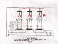
Even same connection diagram for the External CT operated meter where three phase voltage wires directly given to P1,P2, P3,P0. and the current wires via external CT.
:|


l&t electronic energy meter

Just "circle" the place where you are refring as a "short", and upload the cicruit. Professionally the circuit is 100% perfect.
 

l&t energy meters

Ya Please check it out the below diagram what has been highlighted with Red colour.
Actually I have already designed the Web enabled Three Phase Energy meter using ADE7758. So as I was referring this L&T Manual for adding extra features to my project , I gt surprised with this connection diagram. Ofcourse shorting of that doesn't make any sense.


3 phase 4 wire

I am under the impression, that you don't hear well to other contribuitions.

Don't need to repeat myself or others. You may want to consult some basic electrical engineering text book regarding circuit symbols for energy and power meters.

As a very general remark: A straight line in a circuit symbol isn't necessarily a short.
 

three phase connections

...I am speech less....Sorry....Thanks Frank...Its my reply too.
 

ct meter connection

Thank you guys for the great suggestions

Since I am not much aware of these electric symbols used in Energy meter , hope I would get some better clarification from other sources.
 

3 phase 3 wire metering

It's rather simple. Electromechanical meters have been used and are still the standard design for energy meters. https://en.wikipedia.org/wiki/Electricity_meter
They have two coils, a current and a potential coil. https://en.wikipedia.org/wiki/Wattmeter Three phase meters have three individual coil pairs, their energy signal (a mechanical torque) is summed.

The circle with the crossed lines is symbolizing a meter with two coils.
 

Re: 3 Phase 4 Wire Connection for L&T Whole Current Mete

Dear Sanath,
As per my understanding, you question is exactly right. Figure shows that all three phase voltage terminal shorted together, I think it is mistake of L&T drawing.


Regards
Lib
 

Re: energy meter connection

Neutral connections explained
Hi Saneth, There is not a direct short to neutral/earth, u are interperiting the drawing wrong, the large circles are coil representations and a coil needs a neutral connection to allow the flow of electrons, therefore the neutral connections are not a direct short they are simply the neutral connections for the coils, without these the meter would not function!!!!
Also the circles with the crosses in them in the bottom right corner represent the load of the installation, i dont know what the other chap was talking about there!!!!
 

Re: 3 Phase 4 Wire Connection for L&T Whole Current Mete

L&T drawing is perfectly right.The circles with crossed lines represent the power respectively energy metering circuit. It is only a internal connection representation.
 

Status
Not open for further replies.

Similar threads

Part and Inventory Search

Welcome to EDABoard.com

Sponsor

Back
Top