tahertinu
Member level 4
Hi all,
I am working on AC dimmer circuit , for that i have have interfaced the Zero Cross Detection circuit with ATmega16 INT0 pin. INT0 is configured as a rising edge. here i am attaching image which shows the working of Zero cross detection is good. but when i interface its output with ATmega INT0 pin, the Zero Cross Pulsed gets down and nothing happen on INT0 pin. i have tested INT0 code separately which also working as expected. I am not getting where i am doing anything wrong? please somebody help me who has worked with such project ever before
Here is a code snip which gives INT0 routine and Int0 Configuration as rising edge.
When i use this Zero Cross Detection pulses as a normal switch its working good, but when i use it with INT0 pin the pulse get destroyed and nothing happens as attached images
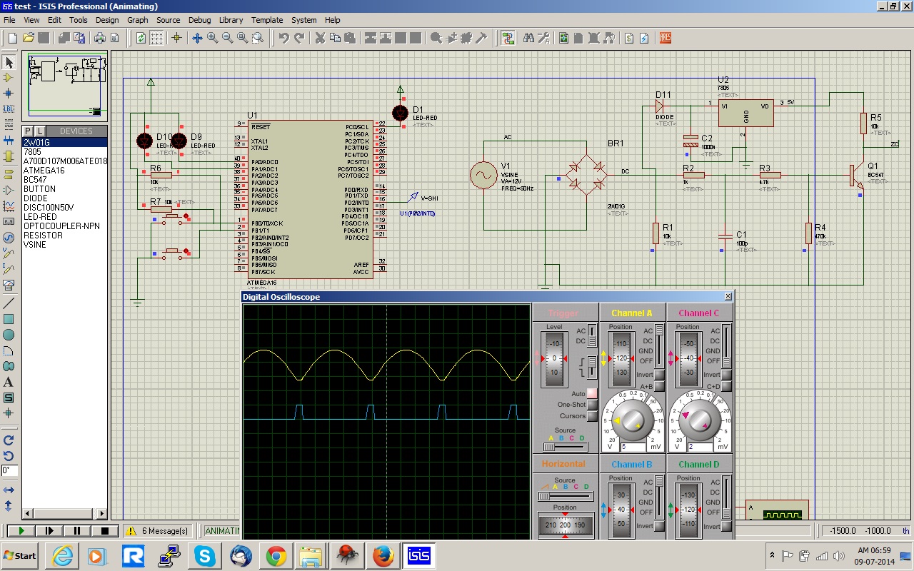
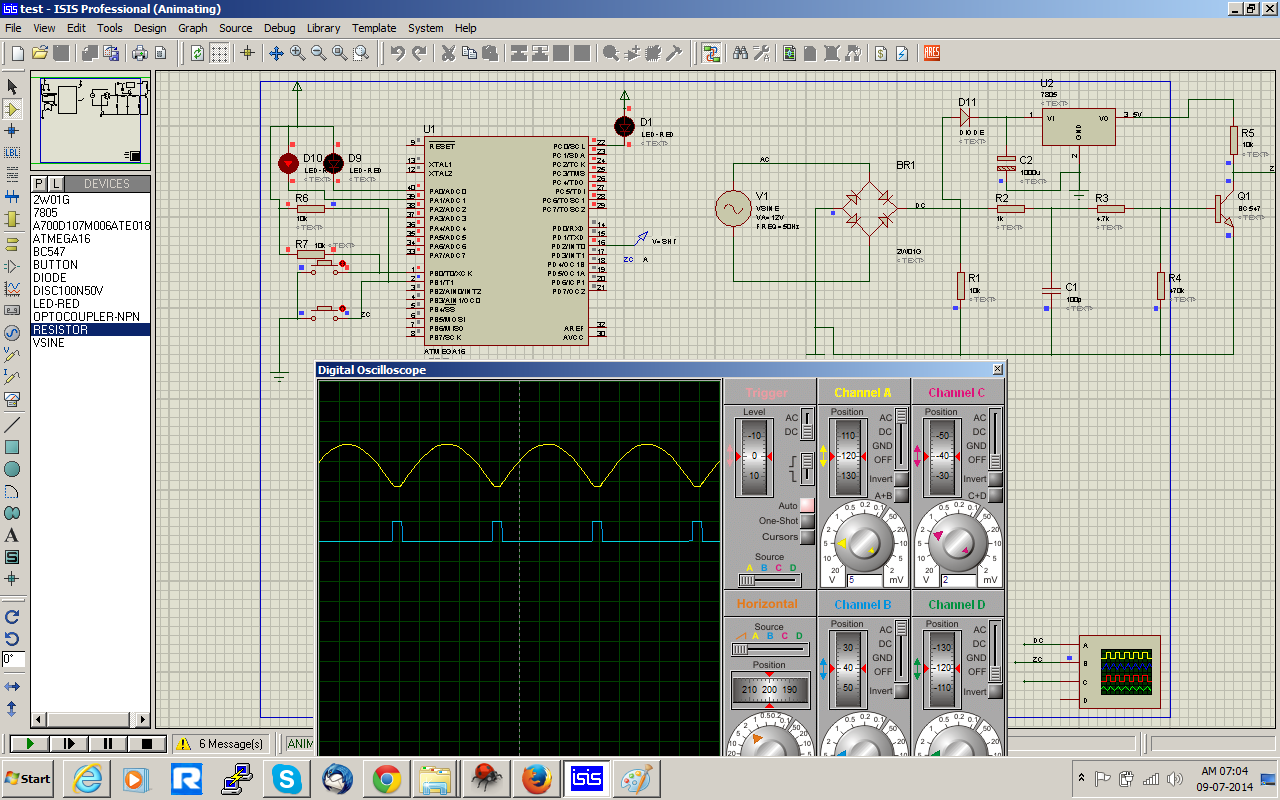
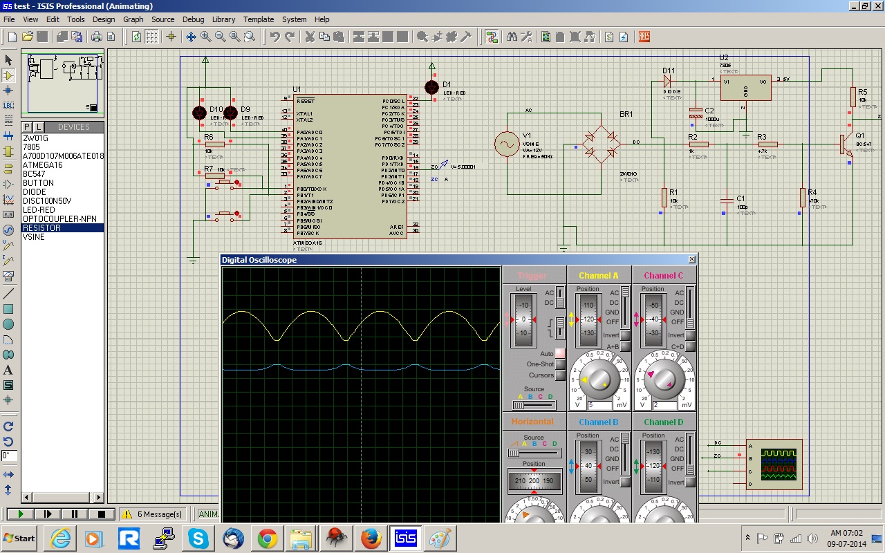
I am working on AC dimmer circuit , for that i have have interfaced the Zero Cross Detection circuit with ATmega16 INT0 pin. INT0 is configured as a rising edge. here i am attaching image which shows the working of Zero cross detection is good. but when i interface its output with ATmega INT0 pin, the Zero Cross Pulsed gets down and nothing happen on INT0 pin. i have tested INT0 code separately which also working as expected. I am not getting where i am doing anything wrong? please somebody help me who has worked with such project ever before
Here is a code snip which gives INT0 routine and Int0 Configuration as rising edge.
Code:
/*
 *  Written in AVR Studio 5 / AVR Studio 6
 *  Compiler: AVR GNU C Compiler (GCC)
 *
 *  Author: AVR Tutorials
 *  Website: www.AVR-Tutorials.com
*/

#include <avr/io.h>
#include <avr/interrupt.h>

#define F_CPU 16000000UL
#include <util/delay.h>

#define DataPort	PORTC	// Using PortC as our Dataport
#define DataDDR		DDRC

//Interrupt Service Routine for INT0
ISR(INT0_vect)
{
	unsigned char i, temp;
	cli();
	//_delay_ms(500); // Software debouncing control

	//temp = DataPort;	// Save current value on DataPort

	/* This for loop blink LEDs on Dataport 5 times*/
	DataPort = 0x00;
	for(i = 0; i<100; i++)
	{

		_delay_us(200);	// Wait 5 seconds

		//_delay_us(200);	// Wait 5 seconds
	}
 	DataPort = 0xFF;
	//DataPort = temp;	//Restore old value to DataPort
	sei();
}

int main(void)
{
	DDRD = 1<<PD2;		// Set PD2 as input (Using for interupt INT0)
	PORTD = 1<<PD2;		// Enable PD2 pull-up resistor

	DataDDR = 0xFF;		// Configure Dataport as output
	DataPort = 0xFF;	// Initialise Dataport to 1

	GICR = 1<<INT0;					// Enable INT0
	MCUCR = 1<<ISC01 | 1<<ISC00;	// Trigger INT0 on rising edge

	sei();				//Enable Global Interrupt
    while(1)
    {
	/*	if(DataPort >= 0x80)
			DataPort = 1;
		else
			DataPort = DataPort << 1;	// Shift to the left

		_delay_ms(500);	// Wait 5 seconds */
		if(!(PIN_1 & (1<<SW_1))) //If switch is pressed
		{
			toggle(LED_PORT,LED_1);
			_delay_ms(1000);
		}
		else if(!(PIN_1 & (1<<SW_2))) //If switch is pressed
		{
		toggle(LED_PORT,LED_2);
		_delay_ms(1000);
		}
    }
}
When i use this Zero Cross Detection pulses as a normal switch its working good, but when i use it with INT0 pin the pulse get destroyed and nothing happens as attached images


")
