Continue to Site

Welcome to EDAboard.com

Welcome to our site! EDAboard.com is an international Electronics Discussion Forum focused on EDA software, circuits, schematics, books, theory, papers, asic, pld, 8051, DSP, Network, RF, Analog Design, PCB, Service Manuals... and a whole lot more! To participate you need to register. Registration is free. Click here to register now.

23cm filter using smd inductors

Status
Not open for further replies.

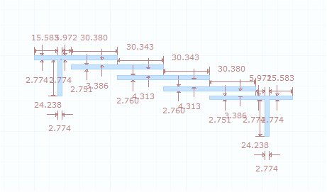
I know that this is microstrip, but look at this one
https://www.qsl.net/va3iul/Homebrew_RF_Circuit_Design_Ideas/Tunable_Combline_uStrip_BPF.gif
it is simple and tuneable.
Have you got any idea what is the source of this circuit? It seems interesting and simple

It's pretty good filter and looks like to the filter which I have already proposed for you.
I have simulated this filter with realistic capacitors from AVX.
Substrate H=1mm, 1/2 oz. copper clad,RO3730 from Rogers Corp.
C1=C2=C3=0.75pF 402 package.
Dimensions=14.1mmx27.1mm
Tunable_Bandpass_Filter.pngTunable_Bandpass_Filter_Response.png
 
Last edited:

Another option to Interdigital Filter is to use Edge Coupled BPF, or Hairpin BPF.
They might use larger PCB area but for example Hairpin BPF provides better rejection and better symmetry.
The simulation use FR4, 1.5mm, Er=4.6, LossTng=0.022

5339977600_1395759666.jpg

2979168000_1395759695.jpg

6200332100_1395759735.jpg

6057730200_1395759762.jpg
 
I like the circuit in post #21 and #22 because it can be made tuneable mechanically by using 1pf smd capacitors in series with some larger value ceramic smd trimmers, or electrically by using 1pf smd capacitors in series with a varicap. From an internet search I believe that if the middle section capacitor is tuned independently from the edges sections ones, the bandwidth of the filter can be also altered.
I am really dump in simulations, could anyone help in doing a simulation of this kind of filter, with the microstrip dimensions shown https://www.qsl.net/va3iul/Homebrew_RF_Circuit_Design_Ideas/Tunable_Combline_uStrip_BPF.gif but instead using an FR4 of 0.8mm thickness and er of about 4.5?
I attach the datasheet of this material.
I would greatly appreciate the help
 

Attachments

  • DS-7405.pdf
    77.9 KB · Views: 86

I like the circuit in post #21 and #22 because it can be made tuneable mechanically by using 1pf smd capacitors in series with some larger value ceramic smd trimmers, or electrically by using 1pf smd capacitors in series with a varicap. From an internet search I believe that if the middle section capacitor is tuned independently from the edges sections ones, the bandwidth of the filter can be also altered.
I am really dump in simulations, could anyone help in doing a simulation of this kind of filter, with the microstrip dimensions shown https://www.qsl.net/va3iul/Homebrew_RF_Circuit_Design_Ideas/Tunable_Combline_uStrip_BPF.gif but instead using an FR4 of 0.8mm thickness and er of about 4.5?
I attach the datasheet of this material.
I would greatly appreciate the help
Here are the results..
C1=C2=C3=GJM0225C1CR60WB01(Murata)
Substrate=FR4,Er=4.5,TanD=0.02,H=0.8mm,T=17.5um (It may also be 35um, no matter)
The insertion Loss is much higher as you due to higher di-electric losses.But the frequency response is not too bad...
Don't add trimmer capacitors because the trimmer capacitors will create some unwanted approximation effects with the other ones and the tuning will be more difficult as a result.
Use these SMD capacitors directly because they have very low tolerances and low profile.You can also use multiple plated vias to improve the GND connection.
If you able to get, use chemically gold plated copper FR laminate ( as an option ) and don't make the filter arms solder resist masking.Let them make open naked..
That's all from me..
Tunable_Bandpass_Filter.pngTunable_Bandpass_Filter_Response.png
 
Last edited:
  • Like
Reactions: neazoi

    neazoi

    Points: 2
    Helpful Answer Positive Rating
Thank you very much for your help!
Indeed if about 1db of loss can be tolerated (in my case it is), cheap FR4 seems that be used.
Do you really think adding these tiny trimmers in series and close to the smd caps could ruin the performance on 23cm?
I have seen large piston capacitors to be used on amateur rod based interdigital fiters.
what about varicaps in series?
 
Status
Not open for further replies.

Similar threads

Part and Inventory Search

Welcome to EDABoard.com

Sponsor

Back
Top